HSA06 Series Pulse Width Modulation Amplifiers

Sales HSA06 Series Pulse Width Modulation Amplifiers

  • Max.Input Vol : 100V
  • Function : BRUSHED DC MOTOR CONTROLLER
  • Max Current : 30A

Product Detail  

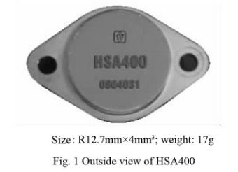
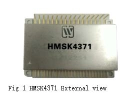
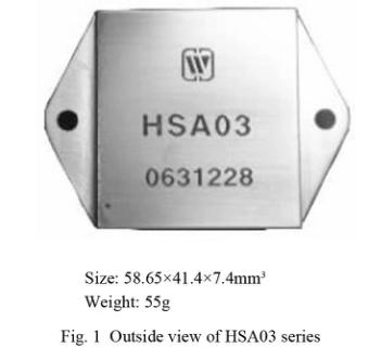
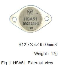
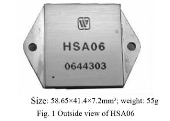
1.Features(for outside view, see Fig. 1)

It can be used interchangeably with SA06 of APEX company.

10A continuous output current (Case temperature ≤75℃)
Thermal protection and programmable external current-limiting protection
Analog and digital input
Synchronous or external oscilloscope
Flexible frequency control


2. Scope of application of HSA06 Series PWMA

Motor control;
Drive reactive load;
Drive low-frequency sonar;
Drive piezoelectric converter;
Offline drive;
C-D welding control.

3. Description of HSA06 Series PWMA

HSA06 is a kind of PWM operation amplifier, which can provide 5kW transmission power for load. There is a 45kHz oscillator inside, the clock input stage halves the oscillator frequency so as to provide the basic 22.5kHz switching frequency. External oscillator can be used to reduce switching frequency or used as synchronous signal of multiple power amplifiers. Shutting off the input end can turn off the four drive tubes of H bridge circuit; has the functions of current limiting and overheat protection.
The series of product adopts thick film hybrid integrated process, sealed in metal case. Design and manufacturing of products shall meet the requirements of GJB2438A-2002 “General specification of hybrid integrated circuit” and detailed specifications for products.

4. Electrical performance (Table 1, Table2) of HSA06 Series PWMA

PWM amplifier (HSA06)

5. Operating principle (Fig. 2) of HSA06 Series PWMA

PWM amplifier (HSA06)PWM amplifier (HSA06)

8. Connection diagram for typical application of HSA06 Series PWMA

HSA06 has two current sampling terminals and , when adopting voltage mode control, these two terminals shall be short-circuited, the typical connection diagram is shown as in Fig. 5; while adopting current control, they shall be connected to sampling resistance and the sampling resistance shall choose non-inductive resistance, the typical connection diagram is shown as in Fig. 2.

PWM amplifier (HSA06)
(1) Bypass of power supply
HSA06 power supply shall have adequate bypass to ensure it runs properly, otherwise, it may be unstable and its efficiency may be reduced and output may oscillate. Vs power supply shall be added with at least 1µF ceramic capacitance, then connected with a bypass capacitance of a low ESR value in parallel, its magnitude shall select 10µF/A at least; for Vcc power supply, it shall also be connected with a 0.1~0.47µF ceramic capacitance in parallel and a 6.8~10µF bypass capacitance of a low ESR value.
(2) Overcurrent protection technology
See Fig. 6 for typical connection under the mode of voltage.
PWM amplifier (HSA06)

Current-limiting control circuit is designed in order to guarantee amplifier operating in safe operation area S0A. Current-limiting value shall not exceed the maximum rated current of the amplifier, otherwise, the amplifier will be damaged.
Because the output current will flow through the current-limiting resistance, its rated power shall be considered, from the point of view of reliability, the resistance value shall be selected as big as possible, and the calculation formulas of current-limiting resistance and its power consumption are as follows:

is the set current-limiting value, at the beginning, set R-Filter and C-Filter to 5kΩ and 0.01µF, respectively.

9. Package specification (unit: mm)(Fig. 7, Table 4) of HSA06 Series PWMA

PWM amplifier (HSA06)
Table 4 Case materials

Case model

Header

Header plating

Cover

Covering plating

Pinmaterial

Pin plating

Sealing style

Notes

UPP4138 -12a

Cold rolled steel (10#)

Ni

Iron/ nickel alloy (4J42)

Ni

Coppercompound

Ni

Compression seal


Note: temperature of the welded pin shall not exceed 300℃ within 10s.

10. Part numbering key (Fig. 8) of HSA06 Series PWMA

PWM amplifier (HSA06)

Application notes

  • Switch on power supply correctly, during the power-up, accurately connect the positive and negative poles of power to avoid burnout.
  • When carrying out the electrical performance test, the test position shall be the pinouts of the product.
  • Upon assembly, the bottom of the product shall fit to the circuit board closely so as to avoid damage of pins, and shockproof provision shall be added, if necessary.
  • Do not bend the pinouts to prevent the insulator from breaking, which affects the sealing property.
  • The circuit shall be added with heat sinking device, and the size of radiator depends upon the output power.
  • When the user places an order for the product, detailed electric performance indexes shall refer to the relevant enterprise standard


Leave A Message
If you are interested in our products and want to know more details,please leave a message here,we will reply you as soon as we can.
X

Home

Supplier

Leave a message

Leave a message

If you are interested in our products and want to know more details,please leave a message here,we will reply you as soon as we can.