HSA03 Series Pulse Width Modulation Amplifiers

Sales HSA03 Series Pulse Width Modulation Amplifiers

  • Max.Input Vol : 100V
  • Function : BRUSHED DC MOTOR CONTROLLER
  • Max Current : 30A

Product Detail  

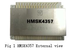
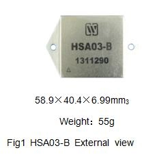
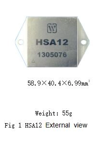
1.Features(see Fig. 1 for outside view, and Table 1 for models)

It can be used interchangeably with SA03 (HSA03) of APEX company.

30A continuous output current (Case temperature ≤60℃)
Thermal protection and programmable external current-limiting protection
Analog and digital input (HSA03)
Synchronous or external oscillator (HSA03)
Flexible frequency control (HSA03)
±10V bipolar input or 3~7V unipolar input (HSA03-1)


2. Scope of application of HSA03 Series PWM Amplifiers

Motor control;
Drive reactive load;
Drive low-frequency sonar;
Drive piezoelectric converter;
Offline drive;
C-D welding control.


3. Description of HSA03 Series PWM Amplifiers

HSA03-1 is a PWM operation amplifier with bipolar input, which can provide maximum power output 3kW for the load. Shutting off the input end can turn off the four drive tubes of H bridge circuit; has the functions of current limiting and overheat protection.
HSA03 is a kind of PWM operation amplifier, which can provide 3kW transmission power for the load. There is a 45kHz oscillator inside, the clock input stage halves the oscillator frequency so as to provide the basic 22.5kHz switching frequency. External clock input signal can be used to reduce switching frequency or used as synchronous signal of multiple operation amplifiers. Shutting off the input end can turn off the four drive tubes of H bridge circuit; has the functions of current limiting and overheat protection.
This series product is made by the thick-film hybrid integration process and is totally sealed in a metal case. Design and manufacturing of products shall meet the requirements of GJB2438A-2002 “General specification for hybrid integrated circuit” and detailed specifications for products.


4. Electrical performance (Table, Table3) of HSA03 Series PWM Amplifiers

Table 2  Rated conditions and recommended operating conditions

Max. absolute rating value

Supply voltage +Vs

+130V(HSA03-1)

+100V(HSA03)

Supply voltage +Vcc

16V

Input voltage: +PWM

±11V(HSA03-1)

0~+11V(HSA03)

Input voltage: -PWM

±11V(HSA03-1)

0~+11V(HSA03)

Input voltage: I

0~+10V

Internal power loss:

380W

Storage temperature

-65~+150℃

Operating temperature (T)

-55~+125℃

Recommended operating condition

Supply voltage +Vs

Supply voltage +Vcc

Input voltage: +PWM

Input voltage I

≤120V(HSA03-1)

100V(HSA03)

15V

+3~+7V(HSA03), -10~+10V(HSA03-1)

0.1V

Storage temperature

Operating temperature (T)

-65~+150℃

-55~+125℃

PWM amplifier (HSA03 series)PWM amplifier (HSA03 series)
Notes: (1) Pin 1 of HSA03-1 is left unconnected (NC); pin 1 of HSA03 is clock input (CLK in).
(2) Pin 2 of HSA03-1 is left unconnected (NC); pin 2 of HSA03 is clock input (CLK in).

7. Connection diagram for typical application of HSA03 Series PWM Amplifiers

HSA03, HSA03-1 have two current sampling ends I and I. When adopting voltage type control, these two terminals shall be shortened, and the typical connection diagram is shown as in Fig. 5; whereas when adopting current type control, these two terminals shall be connected with sampling resistance, the sampling resistance shall choose the non-inductive resistance, the typical connection diagram is shown as in Fig. 2.


PWM amplifier (HSA03 series)
Power supply bypass: HSA03, HSA03-1 power supply shall have adequate bypass to ensure its correct running, or it may not be stable and its efficiency will be reduced, yet the output may oscillate. Vs power supply shall be added with at least 1µF ceramic capacitance, then connected with a bypass capacitance of a low ESR value in parallel, its magnitude shall select 10µF/A at least; for Vcc power supply, it shall also be connected with a 0.1~0.47µF ceramic capacitance in parallel and a 6.8~10µF bypass capacitance of a low ESR value.
Overcurrent protection technology: typical connection diagram under voltage mode (Fig. 6).

PWM amplifier (HSA03 series)

Current-limiting control circuit is designed in order to guarantee amplifier operating in safe operation area S0A. Current-limiting value shall not exceed the maximum rated current of the amplifier, otherwise, the amplifier will be damaged.
Because the output current will flow through the current-limiting resistance, its rated power shall be considered, from the point of view of reliability, the resistance value shall be selected as big as possible, and the calculation formulas of current-limiting resistance and its power consumption are as follows:


,is a set current-limiting value, at the beginning, set R-Filter and C-Filter to 5kΩ and 0.01µF, respectively.

PWM amplifier (HSA03 series)

Application notes:

  • When measuring the output waveform between pin 8 and pin 11 of the product with an oscilloscope, the input power supply plug of the oscilloscope shall be 2-phase.
  • When using it, the case temperature in long term reliable operation of the product shall be T≤65℃.
  • Ensure the correct connection of power supply voltage and input voltage and each voltage value consistent with the requirements in the manual.
  • The conduction tape of pin 5, 7, 8, 9, 11 and 12 of the product, particularly pin 8, 11, shall be widened as wide as possible when designing them so as to ensure reliable operation when high- current passing through them.
  • A bypass of power supply shall be added to ensure the normal operation of the product (see Chapter “Application”).
  • When carrying out the electrical performance test, the test position shall be the pinouts of the product.
  • During the assembly, the bottom of the product shall fit to the circuit board closely so as to avoid damage of pins, and shockproof provision shall be added, if necessary.
  • Bending of pins shall be avoided so as to prevent insulator cracking, which affects the sealing property.
  • The circuit shall be added with heat sinking device, and the size of radiator depends upon the output power.
  • When the user places an order for the product, detailed electric performance indexes shall refer to the relevant enterprise standard.
Leave A Message
If you are interested in our products and want to know more details,please leave a message here,we will reply you as soon as we can.
X

Home

Supplier

Leave a message

Leave a message

If you are interested in our products and want to know more details,please leave a message here,we will reply you as soon as we can.