High-reliability electronic system for aviation , aerospace and some applications of high input transient suppression requirements.
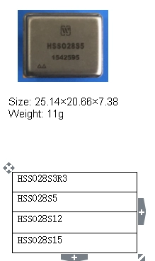
This series products are high reliable DC DC converter featured with transient protection (80 v, 1 s) . Single ended flyback, pulse width modulated and transformer magnetic feedback topology design are used in these products.,The operating principle is that the sampling signal of output voltage, coupled by the transformer, works together with the sampling signal of input loop current to regulate the pulse width of the controller. The double loop control creates constant voltage output. Thick film hybrid techniques provide the HSSO28S Series converters with high reliability and optimum miniaturization. The design and manufacturing process of HSSO28S Series converters are in compliance with MIL-PRF-38534.
Table 2 Rated conditions and recommended operating conditions
|
Absolute Max. Rating |
|
|
Input voltage:12V~50V Input voltage(Transient,1s):80V Output Power:1.62W Storage temperature:-65℃~150℃ |
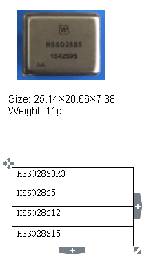
Mechanical Shock:1500g Lead resistance to welding temperature:300℃(15s) Weight:11g Antistatic intensity:2000V |
Table 3 Electrical characteristics
|
No. |
Items |
Condition (Unless other wise,-55℃≤Tc≤125℃,VIN=28V±5%) |
HSSO28S3R3 |
HSSO28S5 |
HSSO28S12 |
||||
|
Min |
Max |
Min |
Max |
Min |
Max |
||||
|
1 |
Input Voltage/V |
Low、High、Ambient Temperature |
12 |
50 |
12 |
50 |
15 |
50 |
|
|
2 |
Output Voltage/V |
Full Load |
Ambient |
3.267 |
3.333 |
4.95 |
5.05 |
11.88 |
12.12 |
|
Low/high |
3.17 |
3.43 |
4.8 |
5.2 |
11.52 |
12.48 |
|||
|
3 |
Output current/A |
VIN=12V~50V |
― |
0.3 |
― |
0.3 |
― |
0.125 |
|
|
4 |
Output Power/W |
|
0 |
1 |
0 |
1.5 |
0 |
1.5 |
|
|
5 |
Output Ripple Voltage/mV |
BW≤20MHz,Full load |
― |
50 |
― |
50 |
― |
50 |
|
|
6 |
Line Regulation/mV |
VIN=12V~50V,Full load |
― |
150 |
― |
150 |
― |
60 |
|
|
7 |
Load Regulation/mV |
10% load →full |
― |
400 |
― |
400 |
― |
700 |
|
|
50% load→full |
― |
250 |
― |
250 |
― |
250 |
|||
|
8 |
Input current/mA |
Inhibited |
― |
3.5 |
― |
3.5 |
― |
3.5 |
|
|
Io=no load |
― |
10 |
― |
10 |
― |
10 |
|||
|
9 |
Input Ripple current/mA |
BW≤20MHz, Full load |
|
30 |
― |
30 |
― |
30 |
|
|
10 |
Efficiency/% |
Full load |
69 |
|
72 |
― |
75 |
― |
|
|
11 |
Isolation/MΩ |
Input to output or any pin to case at 500V,Tc=25℃ |
100 |
|
100 |
― |
100 |
― |
|
|
12 |
Inhibitvoltage |
|
0 |
0.7 |
0 |
0.7 |
0 |
0.7 |
|
|
13 |
Under voltageturn-on voltage/V |
Full load |
6.5 |
11.5 |
6.5 |
11.5 |
6.5 |
11.5 |
|
|
14 |
Short Circuit Protection |
|
With |
With |
With |
||||
|
15 |
/μF |
Tc=25℃ |
- |
500 |
― |
500 |
― |
200 |
|
|
16 |
Full Load |
325 |
475 |
325 |
475 |
325 |
475 |
||
|
17 |
Step Load Response Transient(mV pK) |
50%load→full load or full load→50%load |
-300 |
300 |
-300 |
300 |
-300 |
300 |
|
|
18 |
Step Load Response Recovery(μs) |
50%load→full load or full load→50%load |
― |
500 |
― |
600 |
― |
400 |
|
|
19 |
Step Line Response Transient(mV pK) |
VIN:12V→50V, VIN:50V→12V,Io=Full load |
-300 |
300 |
-400 |
400 |
-400 |
400 |
|
|
20 |
Step Line Response Recovery(μs) |
VIN:12V→50V VIN:50V→12V Io=Full load |
― |
500 |
― |
600 |
― |
400 |
|
|
21 |
Start-up Overshoot(mV pK) |
VIN:0→28V, Io=Full load |
― |
15 |
― |
25 |
― |
50 |
|
|
22 |
Start-up Delay (ms) |
VIN:0→28V, Io=Full load |
― |
20 |
― |
20 |
― |
20 |
|
Form 3(Continued) Electrical characteristics
|
No. |
Items |
Conditions (Unless other wise,-55℃≤Tc≤125℃,VIN=28V±5%) |
HSS028S15 |
||
|
Min |
Max |
||||
|
1 |
Input Voltage/V |
Low、High、Ambient Temperature |
12 |
50 |
|
|
2 |
Output Voltage/V |
Io=Full Load |
Ambient |
14.85 |
15.15 |
|
Low/high |
14.40 |
15.60 |
|||
|
3 |
Output current/A |
VIN=12V~50V |
― |
0.05 |
|
|
4 |
Output Power/W |
|
0 |
1.5 |
|
|
5 |
Output Ripple Voltage/mV |
BW≤20MHz,Full load |
― |
50 |
|
|
6 |
Line Regulation/mV |
VIN=12V~50V,Full load |
― |
60 |
|
|
7 |
Load Regulation/mV |
10% load →full |
― |
700 |
|
|
50% load→full |
― |
250 |
|||
|
8 |
Input current/mA |
Inhibited |
― |
3.5 |
|
|
Io=no load |
― |
10 |
|||
|
9 |
Input Ripple current/mA |
BW≤20MHz,Io=Full load |
― |
50 |
|
|
10 |
Efficiency/% |
Fullload |
76 |
― |
|
|
11 |
Isolation/MΩ |
Input to output or any pin to case at 500V,Tc=25℃ |
100 |
― |
|
|
12 |
Inhibitvoltage |
|
0 |
0.7 |
|
|
13 |
Under voltage open voltage/V |
Full load |
6.5 |
11.5 |
|
|
14 |
Short Circuit Protection |
|
With |
||
|
15 |
/μF |
Tc=25℃ |
― |
200 |
|
|
16 |
Io=Full Load |
325 |
475 |
||
|
17 |
Step Load Response Transient(mV pK) |
50%load→full load or full load→50%load |
-300 |
300 |
|
|
18 |
Step Load Response Recovery(μs) |
50%load→full load or full load→50%load |
― |
400 |
|
|
19 |
Step Line Response Transient(mV pK) |
VIN:12V→50V, VIN:50V→12V,Io=Full load |
-400 |
400 |
|
|
20 |
Step Line Response Recovery(μs) |
VIN:12V→50V VIN:50V→12V Io=Full load |
― |
400 |
|
|
21 |
Start-up Overshoot(mV pK) |
VIN:0→28V, Io=Full load |
― |
50 |
|
|
22 |
Start-up Delay (ms) |
VIN:0→28V, Io=Full load |
― |
20 |
|
|
a. Theoutput load should not be less than 10% of the rated load. |
|||||
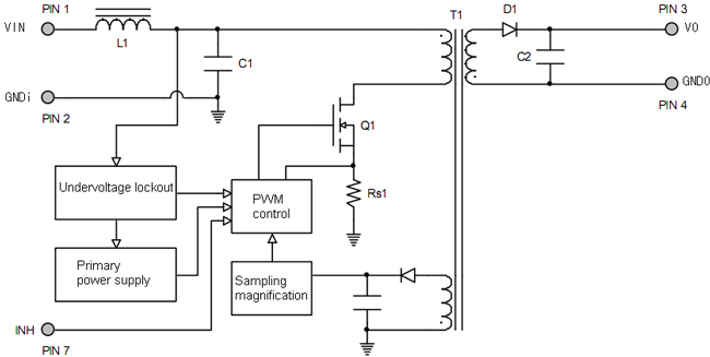
Fig 1 HSSO28S Series circuit block diagram
6. Typical Characteristic Curve of HSSO28S Series of Surge Protection DC DC Converters (Testing condition as per Tc=25℃,VIN=28V±5%,unless otherwise specified)
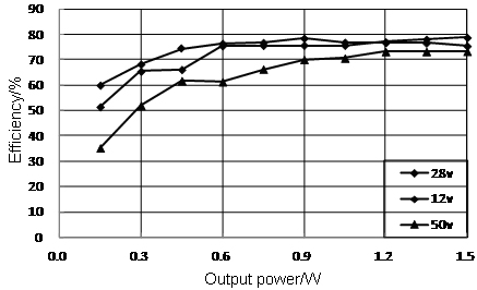
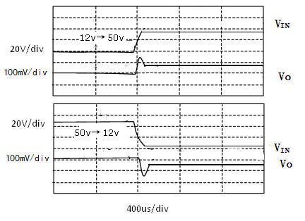
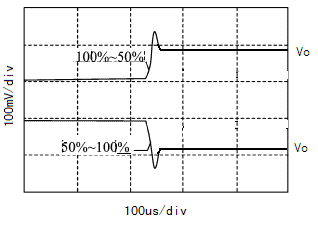
Fig 4 HSSO28S15 Step Load Response
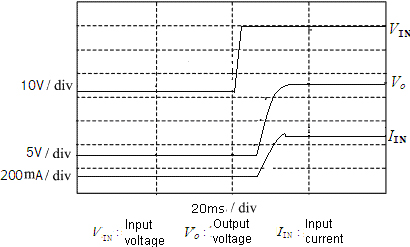
Fig 5 HSSO28S15 Start-up Overshoot/Start-up Delay
7. MTBF Curve of HSSO28S Series of Surge Protection DC DC Converters
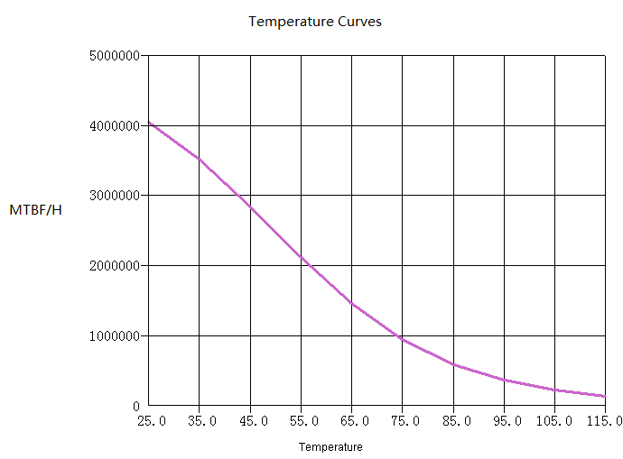
Fig 6 MTBF Temperature Curve(HSSO28S15)
(Well ground condition)
8. Pin Designations of HSSO28S Series of Surge Protection DC DC Converters
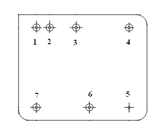
Fig 7 Bottom View
Table 4 Pin Designations
|
Pin |
Symbol |
Designation |
|
1 |
VIN |
Positive input |
|
2 |
GNDI |
Input ground |
|
3 |
VO |
Positive output |
|
4 |
GNDO |
Output ground |
|
5 |
GNDC |
Case ground |
|
6 |
NC |
NC |
|
7 |
INH |
Inhibit |
9. Typical Connection Diagram of HSSO28S Series of Hybrid Surge ProtectionTransient Suppression DC DC Converters
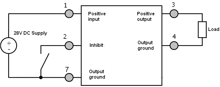
Fig 8 Connection Diagram
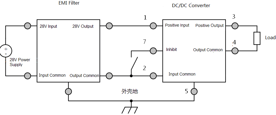
Fig 9 EMI Filter Connection Diagram
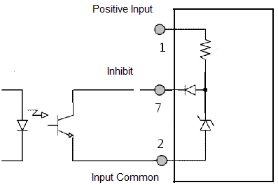
Fig 10 Inhibit Driver Circuit Diagram
10.Package Specifications (Unit: mm) of HSSO28S Series of Surge Protection DC DC Converters

Fig 11 Bottom View
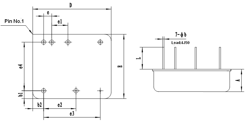
Fig 12 Side View
Table 5 Package Outline
|
Symbols |
Unit/mm |
||
|
Minimum |
Nominal |
Maximum |
|
|
A |
- |
- |
7.38 |
|
фb |
0.32 |
- |
0.58 |
|
b1 |
2.16 |
- |
2.76 |
|
b2 |
3.13 |
- |
3.73 |
|
D |
- |
- |
25.14 |
|
E |
- |
- |
20.66 |
|
e |
2.24 |
2.54 |
2.84 |
|
e1 |
4.78 |
5.08 |
5.38 |
|
e2 |
9.86 |
10.16 |
10.46 |
|
e3 |
17.28 |
17.78 |
18.28 |
|
e4 |
14.74 |
15.24 |
15.74 |
|
L |
5.86 |
- |
- |
|
注:e、e1、e2、e3、e4 are interchangeable size, made by the shell manufacturing and inspection, this specification does not do the assessment requirements. |
|||
Table 6 Case Materials
|
Case Model |
Header |
Header Plating |
Cover |
Cover Plating |
Pin |
Pin Plating |
Sealing |
Notes |
|
UPP2520-07 |
High quality carbon structural steel(08AL) |
Au |
SPCC-SD |
Ni |
4J50 |
Au |
Energy storage welding |
|
11. Ordering Information of HSSO28S Series of Surge Protection DC DC Converters
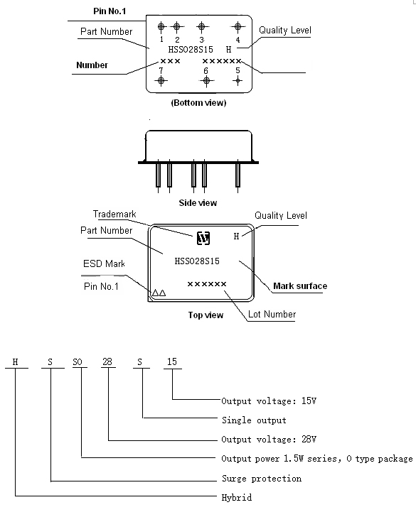
Fig 15 Part Numbering Key
Application Notes:

Subscribe to our weekly newsletter and receive exclusive offers on products you love!
 X
X


 Gold Supplier