Digital to Resolver Converters HDRC14-16 Series

Sales Digital to Resolver Converters HDRC14-16 Series

Digital to Resolver Converters HDRC14-16 Series product is digital to resolver converters or digital to synchro converters of hybrid integrated circuit structure equipped with built-in power amplifier which can drive 2VA load. The load can be inductive load, capacitive load or resistive load, and it is provided with overcurrent and overvoltage protection. The output of converter can directly drive the resolver, and can also drive the control transformer of synchro by connecting a, external transformer.
  • Resolution : 12, 14 or 16 bits
  • Power supply voltage : ±15V
  • Accuracy : ±8.5 arc min(12 bits),±4 arc min(14 bits),±4 arc min(16 bits)

Product Detail  

1.Features (for outside view, see Fig. 1)

14-bit and 16-bit resolution

4′ and 2′ accuracy
2VA output drive capacity
Low radius vector error (0.03%)
Equipped with overvoltage protection and short-circuit protection
Provided with telemetric output pin
Without the need of external adjustment
Pin-to-pin compatibility with DRC1745/1746 product of AD company

2. Scope of application of HDRC14-16 Series Digital to Synchro Converters or Digital to Resolver Converters

Drive synchro/resolver; antenna system; servo system; integrated navigation system; cannon control system; aircraft and warship simulator.

3. Description of HDRC14-16 Series Digital to Synchro Converters or Digital to Resolver Converters

HDRC14/HDRC16 series product is digital to resolver converters or digital to synchro converters of hybrid integrated circuit structure equipped with built-in power amplifier which can drive 2VA load. The load can be inductive load, capacitive load or resistive load, and it is provided with overcurrent and overvoltage protection. The output of converter can directly drive the resolver, and can also drive the control transformer of synchro by connecting a, external transformer.

The unique performance of HDRC14/HDRC16 series product is sine and cosine telemetric output. Thus, when performing long-line drive, it can ensure the precision of converted output signal.

HDRC14/HDRC16 series products are equipped with internal latch, which is controlled through high bit enable end HBE and low bit enable end LBE, and can be connected with data bus conveniently.

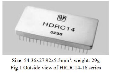
HDRC14/HDRC16 series products are dual in-line 40-pin metal package.

4. Electrical performance (Table 1, Table2) of HDRC14-16 Series Digital to Synchro Converters or Digital to Resolver Converters

Table 1  Rated conditions and recommended operating conditions

Absolute max. rated value

Supply voltage Vs: ± 7.25V

Logic voltage VL: +5.5V

Storage temperature range: -65℃~+150℃

Recommended operating conditions

Supply voltage Vs: ± 5V

Logic voltage VL: +5V

Reference frequency f: 400Hz~2000Hz

Range of operating temperature TA: -55℃~125℃


Table 2  Electric characteristics

Characteristic

HDRC14

HDRC16

Unit

Remarks

Min.

Max.

Min.

Max.

Resolution

-

14

-

16

bit


Angle error

-

±5.3

-

±2

Angular minute


Analogue reference input

3.23

3.57

3.23

3.57

V


Signal output of resolver

6.46

7.14

6.46

7.14

V


Gain

(VRef-Vo)

1.999

2.001

1.999

2.001

V


Temperature coefficient of output gain

-

25

-

25

PPM/℃


Analogue input frequency range

0

2.6

0

2.6

kHz


Analogue input impedance

10.2

-

15.9

-


Analogue output impedance

-

0.2

-

0.2

Ω


Output power

-

2

-

2

VA


Radius vector error

-

±0.03%

-

±0.03%

-


Type of digital input

Parallel binary code (TTL level)

Parallel binary code (TTL level)

-


Fig. 2 Circuit block diagram

5. Power consumption of HDRC14-16 Series Digital to Synchro Converters or Digital to Resolver Converters

At the output stage, common DC power or pulsating power can be used. There is a very low flat top of DC voltage for the pulsating voltage of pulsating power, which reduces the power consumption. At 2VA load, even if the voltage of flat-topped pulsating power is as low as 2~3V, it can also ensure normal operation.
The pulsating power is only used for the gain of supply current at output stage, the total gain of operating circuit in the device does not depend on the power supply, therefore, the conversion accuracy of the device over the full scale range keeps unchanged during the operating period of pulsating power.
Below we will illustrate that when using DC power and pulsating power, the power consumption is different for different load.
(1)DC power supply
For DC power supply, the power consumption related to load is:


Where, Vout is the peak value of output voltage; I1 is the peak value of output load voltage; θ is the digital angle; α is the phase angle of load; VDC is the voltage of DC power, which is normally ±15V.
(2)Pulsating power supply
When using pulsating power supply, the power consumption related to load is:


Where, VAC is the AC component of pulsating voltage, which is assumed to be equal to the peak value Vout of output voltage; I1 is the peak value of output load current; θ is the digital angle; α is the phase angle of load; VP is the flat top of pulsating power.
Note:
Where, Vout=peak value of output voltage=2×VRef;
Z=output load

(3)Example of power consumption
There are many factors that influence the power consumption, the following four examples use typical loads and the worst digital angle state (45º). These examples can illustrate that using pulsating power can reduce the power consumption.
Here, the operating conditions are:
VDC=±15V; Vp=3V; Vout=9.6V (RMS value is 6.8V); VAC=9.6V (approximately equal to Vout); I1=292mA (equivalent to a load which requires 1.4VA).
① DC power supply, θ=45º, resistive load


② Same as example 1, the power supply is 3V pulsating power supply.


When using the pulsating power, the internal power consumption is reduced by 1.75W, their ratio is 3.2:1.
③ DC power supply, θ=45º, pure inductive load


④ Same as example 3, the power supply is 3V pulsating power supply.


(4)Load
Next, we will illustrate how to calculate the load. For the control transformer of synchro, first it is required to obtain the value of Zso, which is generally provided by the synchro manufacturer. The control load is:

Where, V2 is the RMS value of signal voltage.
If an output transformer is added at the output pin, then 0.25VA shall be added to the calculated power.
For example, assume that the RMS value of signal is 90V, 400Hz, use HRDC14 external output transformer to drive the control transformer of synchro. Use of external transformer is to increase the RMS value of voltage output of HRDC14 from 6.8 V to 90V required by the control transformer.
For the control transformer of synchro, Zso is 700+j4900.


Therefore, the load when using the control transformer is:; then plus the additional power consumption of the transformer, the total power consumption is 1.48VA.
This method can also be used for the application that uses the rotary control transformer, but it does not need to be multiplied by 3/4.


6. MTBF curve (Fig. 3) of HDRC14-16 Series Digital to Synchro Converters or Digital to Resolver Converters


Fig. 3  MTBF-temperature curve
(Note: according to GJB/Z299B-98, envisaged good ground condition)

7. Pin designation (fig.4, Table 3) of HDRC14-16 Series Digital to Synchro Converters or Digital to Resolver Converters


Fig.4  Schematic diagram of pin (bottom view)

Table 3  Functional description of pins

Pin

Symbol

Function

Pin

Symbol

Function

Pin

Symbol

Function

1

D1(MSB)

1st bit digital input

13

D13

13th bit digital input

28

GNDA

Analog ground

2

D2

2nd bit digital input

14

D14(LSB)

14th bit digital input

29

V-

-15V Power supply

3

D3

3rd bit digital input

15

D15

15th bit digital input

30

V+

+15V Power supply

4

D4

4th bit digital input

16

D16(LSB)

16th bit digital input

31

V1+

+5V Power supply

5

D5

5th bit digital input

17-20

NC

No connection

32

LE

Low 8-bit select enabled

6

D6

6th bit digital input

21

Vcos

Cosine output end

33

HE

High 8-bit select enabled

7

D7

7th bit digital input

22

Vsin

Sine output end

34

RLo

Low end of reference input

8

D8

8th bit digital input

23

V+P

+15V pulsating power

35

RHi

High end of reference input

9

D9

9th bit digital input

24

V-P

-15V pulsating power

36

Case

Case ground

10

D10

10th bit digital input

25

cos telemetry

Cosine telemetric end

37-40

NC

No connection

11

D11

11th bit digital input

26

sin telemetry

Sine telemetric end


12

D12

12th bit digital input

27

GNDS

Signal ground


Notes: the digital input pin D1~D16 of converter are directly connected with the clear latch for buffer in the converter.
“HBE” controls high 8-bit input and “LBE” controls low-bit input, respectively low 6-bit for HDRC14 and low 8-bit for HDRC 16.
When “HBE” and “LBE” are set to logic “1”, the latch is clear, at this time, the output of converter varies with the change of input data. When “HBE” and “LBE” are set to logic “0”, due to the latching of data at input pin, the data of converter will keep unchanged, until “HBE” and “LBE” are set to logic “1” again. If the latching function is not required, then “HBE” and “LBE” can be open-circuit.
All digital input pins have 27kΩ pull-up resistance inside to be connected with 5V power supply, thus, if 50μA current on any latch input pin leaks to the external digital drive, it can still ensure all input pins compatible with TTL level are stable.

8. Table of weight values (Table 4) of HDRC14-16 Series Digital to Synchro Converters or Digital to Resolver Converters

Table 4  Table of weight values

Bit/(MSB)

Angle

Bit/(MSB)


Angle

Bit/(MSB)

Angle

1

180.000 0

7


2.812 5

13

0.043 9

2

90.000 0

8


1.406 3

14 (for 14-bit LSB)

0.022 0

3

45.000 0

9


0.703 1

15

0.011 0

4

22.500 0

10


0.351 6

16 (for 16-bit LSB)

0.005 5

5

11.250 0

11


0.175 8


6

5.625 0

12


0.087 9


9. Connection diagram for typical application (Fig. 5) of HDRC14-16 Series Digital to Synchro Converters or Digital to Resolver Converters


(1) Signal output type of resolver

(2) Signal output type of synchro (fig.5)


Note: for other voltage output, it is needed to connect an isolation transformer after it (e.g. RTM1683).Fig. 5 Connection diagram for typical application

10. Connection of converter (Fig. 6)
The connection of HDRC14/HDRC16 series product is very direct, i.e. the digital input conforming to the stipulated format in the table of weight values are directly connected to 1(MSB)~14(LSB) of HDRC14 or 1(MSB)~16(LSB) of HDRC16.
ALo and AHi are reference voltage input.
The output amplifier of converter has independent power supply +15V(P) and -15V(P), it is a pulsating power supply, but it can also use DC power supply.+15V and -15V power supply of converter must be DC power supply.
There is a 0.47μF decoupling capacitance between power supplies of power amplification stage inside the converter, but we still recommend to connect a 6.8μF decoupling capacitance between +15V, -15V and GND.
Case means case ground, which can be connected to the suitable zero potential in the system.


Fig. 6 Outside view and dimensions of package

The sin and cos signals are provided by “sin output” and “cos output”. The “sin telemetry” and “cos telemetry” can be directly used, if not, they shall be connected with corresponding sin output pin and cos output pin.

11. Package specifications (unit: mm) (Fig. 7, Table 5) of HDRC14-16 Series Digital to Synchro Converters or Digital to Resolver Converters

Table 5  Case materials

Case model

Header

Header plating

Cover

Covering plating

Pinmaterial

Pin plating

Sealing style

Notes

UP5428-40

Kovar (4J29)

Ni/Au

Iron/ nickelalloy (4J42)

Ni/Au

Kovar (4J29)

Ni/Au

Matchedseal


Note: temperature of the solder pins within 10s shall not exceed 300℃.

12. Part number key (Fig. 7) of HDRC14-16 Series Digital to Synchro Converters or Digital to Resolver Converters


Fig. 7 Part numbering key


Application notes:


  • The voltage of power supply shall not exceed the specified range.
  • Do not connect reference RHi and RLo to other pins.
  • Supply the power correctly, upon power-on, be sure to correctly connect the positive and negative pole of the power supply for fear of burning.
  • Upon assembly, the bottom of the product shall fit to the circuit board closely so as to avoid damage of pins, and shockproof provision shall be added, if necessary.
  • Do not bend the pinouts to prevent the insulator from breaking, which affects the sealing property.
  • When the user places an order for the product, detailed electric performance indexes shall refer to the relevant enterprise standard.
Leave A Message
If you are interested in our products and want to know more details,please leave a message here,we will reply you as soon as we can.
X

Home

Supplier

Leave a message

Leave a message

If you are interested in our products and want to know more details,please leave a message here,we will reply you as soon as we can.