Synchro to Digital Converters or Resolver to Digital Converters (HSDC/HRDC211 Series)

Sales Synchro to Digital Converters or Resolver to Digital Converters (HSDC/HRDC211 Series)

Synchro to Digital Converters or Resolver to Digital Converters (HSDC/HRDC211 Series) is a digital converter of modular structure for synchro/resolver with built-in solid-state SCOTT isolation converter, designed according to the principle of type II servo, and can realize continuous tracking and conversion. 

  • Accuracy : arc min (12bits) ,±5.3 arc min (14bits)
  • Power supply voltage : +5V,±15V,±8.5V
  • Resolution : 10 bits, 12 bits, 14 bits

Product Detail  

1 Features (see Fig. 1 for outside view, and Table 1 for models) of Synchro/Resolver-Digital Converter (HSDC/HRDC211 Series)

Excitation frequency 50Hz, 400Hz and 2.6kHz
Synchro/Resolver-Digital Converter (HSDC/HRDC211 Series)-1
Resolution: 10 bits, 12 bits, 14 bits
High tracking speed
Non-standard input is adjustable through external resistance or adjusted at the product input terminal
DC voltage output directly proportional to angular velocity
Compatible with SDC1700 series of American AD company


2 Scope of application of Synchro to Digital converters or Resolver to Digital Converters (HSDC/HRDC211 Series)

Servo system; antenna system; angle measurement; simulation technology; cannon control; control of industrial machine tools

3 Description of Synchro to Digital converters or Resolver to Digital Converters (HSDC/HRDC211 Series)

HSDC/HRDS211 series is a digital converter of modular structure for synchro/resolver with built-in solid-state SCOTT isolation converter, designed according to the principle of type II servo, and can realize continuous tracking and conversion. 

The operating power is ±15V and + 5V DC power. There are two types of output signal: three-line synchro and reference signal (SDC converter) or four-line resolver and reference signal (RDC converter); the output is parallel digital codes of binary system.

4 Electrical performance (Table 2, Table 3) of Synchro to Digital converters or Resolver to Digital Converters (HSDC/HRDC211 Series)


Table 2  Rated conditions and recommended operating conditions

Absolute max. rated value

Supply voltage Vs: ± 17.5V

Logical voltage VL: +7V

Storage temperature range: -55℃~105℃

Recommended operating conditions

Supply voltage Vs: ±15V

5V logic supply voltage VL: +5V

Effective value of reference voltage VRef: 11.8V, 26V, 115V

Effective value of reference voltage V1*: 11.8V, 26V, 90V

Reference frequency f*: 50Hz, 400Hz, 2.6kHz

Operating temperature range TA: 0~70℃, -40~+85℃

Note: * indicates it can be customized as per user’s requirement.


5 Operating principle of Synchro to Digital converters or Resolver to Digital Converters (HSDC/HRDC211 Series)

The synchro input signal (or input signal of resolver) is converted into the orthogonal signal through internal differential isolation:
Synchro/Resolver-Digital Converter (HSDC/HRDC211 Series)-2
Synchro/Resolver-Digital Converter (HSDC/HRDC211 Series)-3
Where, θ is analog input angle
The orthogonal signal is multiplied by the binary digital angle φ in the internal reversible counter in the sine-cosine function multiplier and an error function is obtained:

The signals are sent to voltage controlled oscillator after amplification, phase discrimination and integration filtration, if θ-φ≠0, the voltage controlled oscillator will output pulse to change the data in the reversible counter, till θ-φ becomes zero within the accuracy of the converter, during this process, the converter tracks the change of input angle θ all the time. For working principle, see Fig. 2.
Transfer function: following are parameters for transfer function of HSDC2112 and HSDC2114(400Hz), for other models, please contact the manufacturer directly.
Synchro/Resolver-Digital Converter (HSDC/HRDC211 Series)-5
Fig.2 Block diagram for operating principle of the converter

Synchro/Resolver-Digital Converter (HSDC/HRDC211 Series)-6
(1)Data transfer
There are two methods for reading out the valid data of converter as follows:
 Inhibit method (synchronous reading):
Set Inhibit to logic “0”, at this time, the converter will stop tracking. Wait for 1μs till the output data is stable, read the data, the data read is the valid one at this time (1μs has been delayed).Set  to logic “1”, at this time, the converter will start tracking again in order to get ready for reading next valid data.
Busy method (asynchronous reading):Inhibit
In asynchronous reading mode, is set to logic “1” or vacant, if the internal loop is always in stable state or if the output data is valid shall be determined through the state of busy signal Busy. When Busy signal is at high level, it indicates the data is being converted, and the data at this time is unstable and invalid; when Busy signal is at low level, it indicates the data conversion has been completed, and the data at this time is stable and valid. In asynchronous reading mode, Busy output is pulse train of TTL level, the width between is related to rotational speed. Refer to time sequence diagram of data transfer Fig. 3.
Synchro/Resolver-Digital Converter (HSDC/HRDC211 Series)-13
Fig.3 Time sequence of data transfer

(2)Attenuation method of input signal
If the synchro or resolver the user used is non-standard, in order to make the input signal voltage and input excitation voltage match the nominal values of the converter, the user may adopt the method of external attenuation resistance connected in series, i.e. for every 1V exceeding the nominal value, connect 1.1kΩ resistance in series at the corresponding input terminal. When using the converter, the series resistance at each terminal shall be precisely selected and furnished, and resistance material of the same lot shall be adopted so as to ensure the conversion accuracy of the converter within the wide temperature range, for every 0.1% the matching error of the series resistance will generate 1.7 angular minute conversion error.
It is recommended by the manufacturer that it is preferable to notify the manufacturer to customize the non-standard synchro or resolver as per the required parameters when the user uses them.

6 MTBF curve (Fig. 4) of Synchro to Digital converters or Resolver to Digital Converters (HSDC/HRDC211 Series)

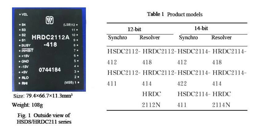
7 Pin designation (Fig. 5, Table 4) of Synchro to Digital converters or Resolver to Digital Converters (HSDC/HRDC211 Series)


Fig. 4  MTBF-temperature curve
(Note: according to GJB/Z299B-98, envisaged good ground condition)
Notes:
① the above structure is suitable for HRDC2114
② for SDC, no pin S4
③ for 12-bit device, no pin 13 and 14, for 10-bit device, no pin 11, 12, 13 and 14.
Fig.5 Pin designation (Top view)

Table 4 Pin designation

Pin

Symbol

Function

Pin

Symbol

Function

1

D1

Digital outputofbit 1 (MSB)

15

Vel

Angular velocity voltage output

2

D2

Digital outputofbit 2

16

S4

Signal input

3

D3

Digital outputofbit 3

17

S3

Signal input

4

D4

Digital outputofbit 4

18

S2

Signal input

5

D5

Digital outputofbit 5

19

S1

Signal input

6

D6

Digital outputofbit 6

20

Busy

Busy signal input

7

D7

Digital outputofbit 7

21

Inhibit signal input

8

D8

Digital outputofbit 8

22

+15V

+15V Power supply

9

D9

Digital outputofbit 9

23

GND

Ground

10

D10

Digital outputofbit 10 (10-bit LSB)

24

-15V

-15V Power supply

11

D11

Digital outputofbit 11

25

+5V

+5V Power supply

12

D12

Digital outputofbit 12 (10-bit LSB)

26

RLo

Low end of reference signal input

13

D13

Digital output of bit 13

27

RHi

High end of reference signal input

14

D14

Digital outputofbit 14 (10-bit LSB)


Notes:
Power supply: ± 15V, +5V, GND
Binary digital output: 10 bits, 12 bits and 14 bits, respectively.
RHi, RLo: excitation signal input.
S1, S2, S3 and S4: signal input of synchro or resolver.(S4 not used for the synchro)
Vel: velocity signal. It is a voltage signal, the value of which is proportional to the angular rotational speed of the shaft.
Busy: busy signal. It indicates if the converter data is being in the updating state. When Busy is at high level, it indicates the converter is carrying out data conversion, the data output at this time is invalid; when Busy is at low level, the data in the converter is stable and the data output at this time is valid.
⑦Inhibit : This is an external inhibit signal. By this signal, the internal tracking status can be controlled, when it is logic “1”, the converter is in normal tracking status inside, at this time, Busy signal indicates whether the output data is valid or not, when Inhibit is logic “0”, the converter stops tracking the status temporarily, the output data remains stable and is the valid output data. When Inhibit is logic “1”, the converter will start tracking again (the maximum recovery time is approximately equal to the maximum step response time). This pin has been pulled up inside.

8 Table of weight values (Table 5) of Synchro to Digital converters or Resolver to Digital Converters (HSDC/HRDC211 Series)

Table 5  Table of weight values
Synchro/Resolver-Digital Converter (HSDC/HRDC211 Series)-16

9 Connection diagram for typical application (Fig. 6) of Synchro to Digital converters or Resolver to Digital Converters (HSDC/HRDC211 Series)

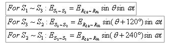
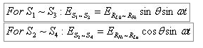
(1) Connection of the converter
±15V, +5V and GND shall be connected to corresponding pins on the converter, notice that the polarities of the power supply must be correct, otherwise, the converter may be damaged. It is recommended to connect 0.1μF and 6.8μF bypass capacitance in parallel between each power supply terminal and ground.
Signal and excitation source are allowed to be connected to S1, S2, S3 and S4 and RHi and RLo terminal within an error of 5%.
The signal input shall match the phase of the excitation source so that they can be correctly connected with the converter, their phases are as follows:
Synchro/Resolver-Digital Converter (HSDC/HRDC211 Series)-18

Fig.6 Connecting diagram of typical application

For the synchro, signal inputs are:


For the resolver:


Note: no input signal of RHi, RLo, S1, S2, S3 and S4 is not allowed to be connected to other pins for fear of damage of the device.
(2) Interface with computer
In order to prevent data collection during high level of the Busy pulse and to ensure to acquire valid data, connection in Fig.7 can be adopted:
(3) Application of the converter
Besides being directly used in precise measurement of rotational angle of the synchro or resolver, the shaft angle converter can also constitute two-speed measurement system or other digital measurement control system of higher precision.
Fig. 8 is an example of two-speed system composed of the converter. The two-speed system established on the principle of combination of coarse and precise measurement has a higher conversion precision, the figure shows the two-speed conversion system composed of two synchros (or resolvers) coupled through the gearbox, two SDC converters and a two-speed processor HTSL19, its output reaches 19 bits.
Synchro/Resolver-Digital Converter (HSDC/HRDC211 Series)-25
Fig.8 Application of two-speed system of SDC
Synchro/Resolver-Digital Converter (HSDC/HRDC211 Series)-24
Fig.7 A feasible external computer interface circuit

Fig.9 shows a digital control servo system. It utilizes the negative feedback loop of digital control constituted by SDC to achieve precision control of the rotational angle.

10 External dimensions and description of package (unit: mm) (Fig.10) of Synchro to Digital converters or Resolver to Digital Converters (HSDC/HRDC211 Series)

Synchro/Resolver-Digital Converter (HSDC/HRDC211 Series)-26
Synchro/Resolver-Digital Converter (HSDC/HRDC211 Series)-27
Fig.9 Digital control servo system
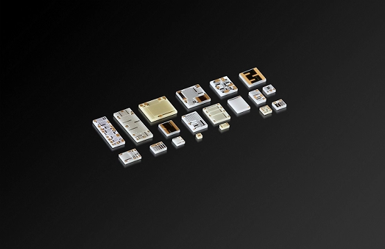
Fig.10 Outside view of package

11 Part numbering key (Fig. 11) of Synchro to Digital converters or Resolver to Digital Converters (HSDC/HRDC211 Series)


Synchro/Resolver-Digital Converter (HSDC/HRDC211 Series)-28
Fig.11 Part numbering key of Synchro to Digital converters or Resolver to Digital Converters (HSDC/HRDC211 Series)

Note: when the above signal voltage and reference voltage (Z) are non-standard, they shall be given as follows:
Synchro/Resolver-Digital Converter (HSDC/HRDC211 Series)-29
(e.g. reference voltage 5V and signal voltage 3V are expressed as -5/3)

Application notes:
  • Supply the power correctly, upon power-on, be sure to correctly connect the positive and negative pole of the power supply for fear of burning.
  • Upon assembly, the bottom of the product shall fit to the circuit board closely so as to avoid damage of pins, and shockproof provision shall be added, if necessary.
  • When the user places an order for the product, detailed electric performance indexes shall refer to the relevant enterprise standard.
Leave A Message
If you are interested in our products and want to know more details,please leave a message here,we will reply you as soon as we can.
X

Home

Supplier

Leave a message

Leave a message

If you are interested in our products and want to know more details,please leave a message here,we will reply you as soon as we can.