|
Single power supply |
|
|
Widely input supply voltage range:16V~100V |
|
|
Continuous output current:20A |
|
|
Current-limiting protection function |
|
|
Recommended operating conditions |
|
Supply voltage +VS:100V Output peak current:30A Internal power loss:185W Storage temperature:-65~+150℃ Operating Temperature:-55~+125℃
|
Supply voltage +VS:50V Turn-off voltage:0.18V~0.22V Turn-off current:100nA
|
|
No |
Character |
Conditions -55℃≤Tc≤125℃ |
HSA01 |
Symbol |
||
|
min |
Typical value |
max |
||||
|
1 |
Switching frequency |
- |
35.3 |
42 |
48.7 |
KHZ |
|
2 |
Output efficiency |
VS=100V,IO=10A |
- |
97 |
- |
% |
|
3 |
Continuous working current |
package temperature below 60℃ |
- |
20 |
- |
A |
|
4 |
Peak working current |
- |
- |
30 |
- |
A |
|
5 |
Power supply+VS |
- |
16 |
50 |
100 |
V |
|
6 |
Power supply current |
IO=0 |
- |
- |
90 |
MA |
|
7 |
Turn-off threshold voltage Vlimit |
- |
0.18 |
- |
0.22 |
V |
|
8 |
Turn-off threshold current Ilimit |
- |
- |
- |
100 |
MA |
|
9 |
Range of working temperature(Package temperature TC) |
- |
-55 |
- |
+125 |
℃ |

|
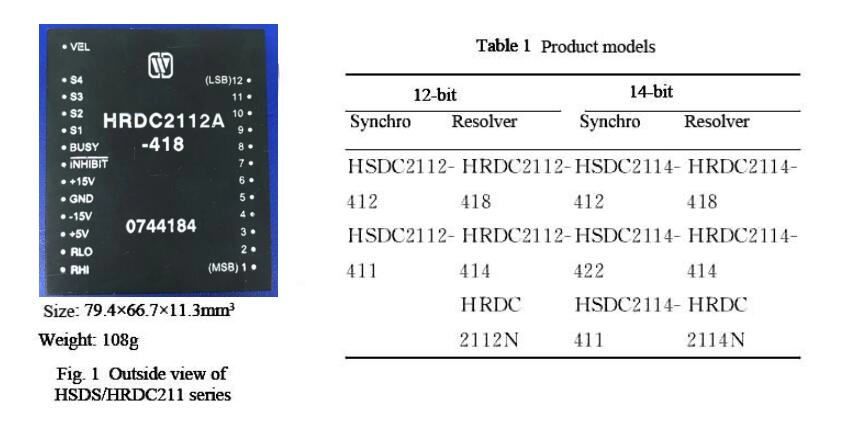
No |
symbol |
Designation |
No |
symbol |
Designation |
|
1 |
-In |
Opposed phrase input |
6 |
Aout |
Output A |
|
2 |
+In |
in phrase input |
7 |
+Vs |
Power supply +Vs |
|
3 |
EAOUT |
error amplifier output |
8 |
ISENSE |
current induction terminal |
|
4 |
GND |
ground |
9 |
BOUT |
Output B |
|
5 |
VRef |
reference voltage output |
10 |
IIlimit /SHDN |
Current limiter/Turn off |


Fig 6 package outline drawing
Form 4 Package Outline
|
Symbol |
Data/mm |
||
|
Min |
Typical |
Min |
|
|
A |
6.5 |
- |
6.7 |
|
A1 |
- |
2.4 |
- |
|
Φb |
1.4 |
1.5 |
1.6 |
|
D |
31.3 |
- |
31.5 |
|
E |
- |
- |
33.15 |
|
e |
- |
5.08 |
- |
|
e1 |
22.61 |
22.86 |
23.11 |
|
L |
11.7 |
12.0 |
12.3 |
|
X1 |
- |
41.5 |
- |
|
X |
49.9 |
50.2 |
50.5 |
|
ΦP |
- |
4.0 |
- |

Subscribe to our weekly newsletter and receive exclusive offers on products you love!
 X
X


 Gold Supplier