|
75V volt of motor power supply |
 |
|
10A output current converter capability,All N channel MOS-FET Output bridge type |
|
|
100% dead-high transmission capacity |
|
|
Suitable for DC to 100KHZ AC PWM |
|
|
Short down/cross conduct protection |
|
|
Protection for under-voltage lockout |
|
|
Control for programmable dead-time |
|
|
Control for active shutoff by low level |
|
|
Isolated package design provides high voltage insulation and excellent heat transmission performance |
|
| Working for optional three-foot bending |
|
Parameter |
Test condition |
A group④ |
MSK4300H③ |
MSK4300② |
Unit |
|||||||||||||||
|
Control choice |
|
|
min |
Typical |
max |
min |
Typical |
max |
|
|||||||||||
|
Static bias current |
Shut off all the input |
1,2,3 |
|
2.5 |
8 |
|
2.5 |
8 |
mA |
|||||||||||
|
Working current |
Frequency=20KHZ,50% duty cycle |
1,2,3 |
|
12.5 |
15 |
|
12.5 |
15 |
mA |
|||||||||||
|
Undervoltage threshold value(decline) |
|
1 |
5.75 |
6.6 |
7.5 |
5.75 |
6.6 |
7.5 |
V |
|||||||||||
|
Undervoltage threshold value (rise) |
|
1 |
6.2 |
7.1 |
8 |
6.2 |
7.1 |
8 |
V |
|||||||||||
|
Low level input voltage① |
|
- |
- |
- |
0.8 |
- |
- |
0.8 |
V |
|||||||||||
|
High level input voltage① |
|
- |
2.7 |
- |
- |
2.7 |
- |
- |
V |
|||||||||||
|
Low level input current① |
VIN=0V |
- |
60 |
100 |
135 |
60 |
100 |
135 |
Microampere |
|||||||||||
|
High level input current① |
VIN=5V |
- |
-1 |
- |
+1 |
-1 |
- |
+1 |
Microampere |
|||||||||||
|
Output bridge |
||||||||||||||||||||
|
Drain-source breakdown voltage |
ID=25μA, shut off all the input |
- |
70 |
- |
- |
70 |
- |
- |
V |
|||||||||||
|
Drain-source leakge current |
VDS=70V |
- |
- |
- |
25 |
- |
- |
25 |
Microampere |
|||||||||||
|
Drain-sourceturn-on resistance(each FET) |
ID=10A |
1 |
- |
- |
0.3 |
- |
- |
0.3 |
Ohm |
|||||||||||
|
Drain-sourceturn-on resistance (FET,just forthermal calculation)① |
|
- |
- |
- |
0.16 |
- |
- |
0.16 |
Ohm |
|||||||||||
|
Switching characteristic |
||||||||||||||||||||
|
Rise time |
V+=30V,RL=3Ω |
- |
5 |
- |
- |
5 |
- |
Nanosecond |
|
|||||||||||
|
Decline time |
ID=10A |
- |
- |
- |
- |
6 |
- |
Nanosecond |
|
|||||||||||
|
Conduction delay(down) |
SWR resistance=∞ |
4 |
- |
0.5 |
2 |
- |
0.5 |
3 |
Microsecond |
|||||||||||
|
Shut off delay(down) |
SWR resistance=∞ |
4 |
- |
5 |
8 |
- |
5 |
10 |
Microsecond |
|||||||||||
|
Conduction delay(up) |
SWR resistance=∞ |
4 |
- |
5 |
8 |
- |
5 |
10 |
Microsecond |
|||||||||||
|
Shut off delay(up) |
SWR resistance=∞ |
4 |
- |
0.5 |
2 |
- |
0.5 |
3 |
Microsecond |
|||||||||||
|
Dead time |
SWR resistance=∞ |
4 |
6 |
7 |
8 |
6 |
7 |
8 |
Microsecond |
|||||||||||
|
Dead time |
SWR resistance 12K |
4 |
0.3 |
0.5 |
0.7 |
0.3 |
0.5 |
0.7 |
Microsecond |
|||||||||||
|
Source –Drain diode characteristics |
||||||||||||||||||||
|
Forward voltage① |
ISD=10A |
- |
- |
1.05 |
1.25 |
- |
1.05 |
1.25 |
V |
|||||||||||
|
Reverse recover time① |
ISD=10A,di/dt=100A/μS |
- |
- |
75 |
- |
- |
75 |
- |
Nanosecond |
|||||||||||
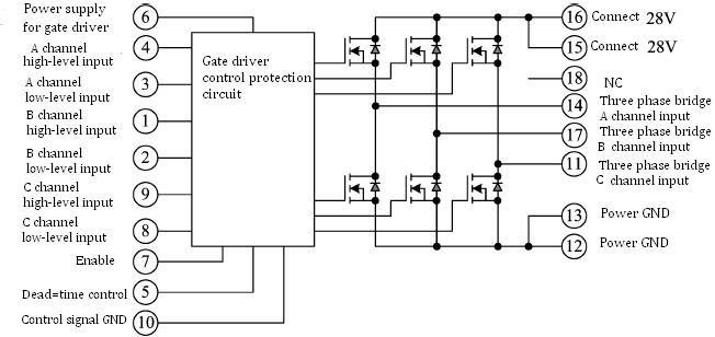
|
Pin |
Symbol |
Designation |
Pin |
Symbol |
Designation |
|
1 |
BH′ |
B channel high-level logic signal input |
6 |
VBIAS |
Power supply for gate Drive |
|
2 |
BL |
B channel low-level logic signal input |
7 |
EN′ |
Working enable for system |
|
3 |
AL |
A channel low-level logic signal input |
8 |
CL |
C channel low-level logic signal input |
|
4 |
AH′ |
A channel high-level logic signal input |
9 |
CH′ |
C channel high-level logic signal input |
|
5 |
SWR′ |
Dead time control |
10 |
GND |
GND |
|
11 |
CΦ |
Three-phase bridge C channel output |
12 |
RSENSE |
Power GND |
|
13 |
RSENSE |
Power GND |
14 |
AΦ |
Three-phase bridge A channel output |
|
15 |
V+ |
+28V |
16 |
V+ |
Connect +28V |
|
17 |
BΦ |
Three-phase bridge B channel output |
18 |
NC |
suspend |


 X
X