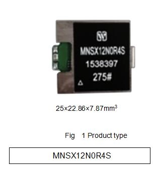
MNSX12N0R4S DC to DC Converter is used in aerospace high reliable electronic system.
3. Descriptions of MNSX12N0R4S High Reliability Point of Load DC to DC Converters (POL)
MNSX12N0R4S point of load DC/DC converter uses BUCK-BOOST topological structure. Circuit contains input filter, PWM control, and reactive circuit and so on. Circuit also has protected function for over-current and under-voltage to improve the reliability.
The MNSX12N0R4S point of load DC/DC converter is modular circuit structure; it’s used by PCB surface assembly process, no embedment, package is used by 2014 mucilage glue, gushing three proofing, and copper shell.
|
Absolute max rating |
Recommended condition |
|
Input voltage:18V Output power:4.8W Storage temperature:-45~105℃ Leads resistance welding temperature(10s):< 300℃ Junction temperature:< 150℃ |
Input voltage:7~18V working temperature range(Tc):-40~85℃ |
|
No. |
Characteristic |
Symbol |
Conditions (otherwise specified,-40℃≤Tc≤85℃,VIN=12V±0.5V) |
Limit value |
Unit |
|
|
min |
max |
|||||
|
1 |
Input voltage |
Vo |
VI=7V-18V,Io=0.05A-0.4A |
-12.15 |
-11.85 |
V |
|
2 |
Output current |
Io |
VI=7V-18V |
0.05 |
0.4 |
A |
|
3 |
Output ripple voltage(peak-peak) |
VP-P |
TA=25℃,BW≤20MHz, full load |
- |
120 |
mV |
|
4 |
Voltage regulation rate |
Sv |
full load,VI=7V 18V |
- |
0.5 |
% |
|
5 |
Load regulation rate |
SI |
Io=0.05A 0.4A |
- |
1 |
% |
|
6 |
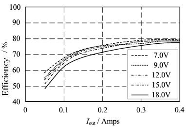
Efficiency |
η |
TA=25℃, full load |
75 |
- |
% |


|
No.
|
Symbol |
Function |
|
1 |
VI |
Inputpositive |
|
2 |
Vo |
Output -12V |
|
3 |
GND |
Input Output common |
|
4 |
GNDC |
Package common |
|
5 |
GNDC |
Package common |


|
Symbol |
Data/mm |
||
|
Min |
Typical |
Min |
|
|
A |
- |
- |
22.86 |
|
B |
- |
- |
23.87 |
|
C |
- |
- |
7.87 |
|
Ψd |
0.47 |
- |
0.73 |
|
e1 |
- |
2.54 |
- |
|
e2 |
- |
5.08 |
- |
|
e3 |
- |
11.4 |
- |
|
e4 |
- |
25.4 |
- |
|
F1 |
1.0 |
- |
1.6 |
|
F1 |
0.1 |
- |
0.7 |
|
L1 |
3.55 |
- |
- |
|
L2 |
1.15 |
- |
1.75 |


Subscribe to our weekly newsletter and receive exclusive offers on products you love!
 X
X


 Gold Supplier