|
Absolute max rating |
Recommended condition |
|
Input voltage:25V Output power:5W Storage temperature:-45~105℃ Leads resistance welding temperature(10s):< 300℃ Junction temperature:< 150℃ |
Input voltage:7~25V Working temperature range(Tc):-40~85℃ |
|
No. |
Characteristic |
Symbol |
Conditions (otherwise specified,-40℃≤Tc≤85℃,VIN=16V±0.5V) |
Limit value |
Unit |
|
|
min |
max |
|||||
|
1 |
Input voltage |
Vo |
VI=7V-25V,Io=0.1A-1A |
-5.1 |
-4.9 |
V |
|
2 |
Output current |
Io |
VI=7V-25V |
0.05 |
1 |
A |
|
3 |
Output ripple voltage(peak-peak) |
VP-P |
TA=25℃,BW≤20MHz, full load |
- |
120 |
mV |
|
4 |
Voltage regulation rate |
Sv |
full load,VI=7V 25V |
- |
0.5 |
% |
|
5 |
Load regulation rate |
SI |
Io=0.05A 0.1A |
- |
1 |
% |
|
6 |
Efficiency |
η |
TA=25℃, full load |
75 |
- |
% |


|
No.
|
Symbol |
Function |
|
1 |
VI |
Inputpositive |
|
2 |
Vo |
Output -5V |
|
3 |
GND |
Input Output common |
|
4 |
GNDC |
Package common |
|
5 |
GNDC |
Package common |


|
Symbol |
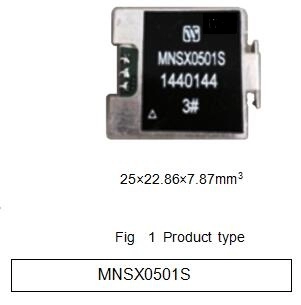
Data/mm |
||
|
Min |
Typical |
Min |
|
|
A |
- |
- |
22.86 |
|
B |
- |
- |
23.87 |
|
C |
- |
- |
7.87 |
|
Ψd |
0.47 |
- |
0.73 |
|
e1 |
- |
2.54 |
- |
|
e2 |
- |
5.08 |
- |
|
e3 |
- |
11.4 |
- |
|
e4 |
- |
25.4 |
- |
|
F1 |
1.0 |
- |
1.6 |
|
F1 |
0.1 |
- |
0.7 |
|
L1 |
3.55 |
- |
- |
|
L2 |
1.15 |
- |
1.75 |


Subscribe to our weekly newsletter and receive exclusive offers on products you love!
 X
X


 Gold Supplier