|
|
|
|
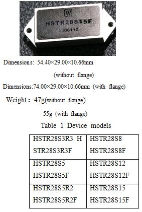
Input voltage:15V~50V Input voltage(Transient,1s):80V Output Power:41.5W Storage temperature:-65℃~150℃ |
Mechanical Shock:1500g Lead resistance welding temperature:300℃(15s) Weight(without flange/ with flange):47g/55g Antistatic intensity:2000V |
| No. | Items | Conditions | HSTR28S3R3 | HSTR28S5R2 | HSTR28S8 | |||||||
| HSTR28S3R3F | HSTR28S5R2F | HSTR28S8F | ||||||||||
| Min | Max | Min | Max | Min | Max | |||||||
| 1 | Input Voltage/V | Low、High、Ambient Temperature | 15 | 50 | 15 | 50 | 15 | 50 | ||||
| 2 | Output Voltage/V | Io=Full | Ambient | 3.25 | 3.35 | 5.14 | 5.26 | 7.92 | 8.08 | |||
| Load | Low/high | 3.2 | 3.4 | 5.07 | 5.33 | 7.88 | 8.12 | |||||
| 3 | Output current/A | VIN=15V~50V | ― | 6.06 | ― | 6 | ― | 4.4 | ||||
| 4 | Output Power/W |
|
0 | 20 | 0 | 31 | 0 | 35 | ||||
| 5 | Output Ripple Voltage/mV | BW=6MHz,Io=Full | ― | 50 | ― | 50 | ― | 50 | ||||
| load | ||||||||||||
| 6 | Line Regulation/mV | VIN=15V~50V,Io=Full | ― | 20 | ― | 20 | ― | 20 | ||||
| 7 | Load Regulation/mV | Io=No load to load | ― | 50 | ― | 50 | ― | 50 | ||||
| 8 | Input current/mA | Inhibit | ― | 6 | ― | 6 | ― | 6 | ||||
| Io=no load | ― | 60 | ― | 60 | ― | 60 | ||||||
| 9 | Input Ripple current/mA | BW=20MHz,Io=Full | ― | 50 | ― | 50 | ― | 50 | ||||
| load | ||||||||||||
| 10 | Efficiency/% | Io=Full | 65 | ― | 72 | ― | 74 | ― | ||||
| load | ||||||||||||
| 11 | Isolation/MΩ | Input to output or any pin to case(except pin 7、8)at 500V,TA=25℃ | 100 | ― | 100 | ― | 100 | ― | ||||
| 12 | Inhibit Function |
|
0 | 0.7 | 0 | 0.7 | 0 | 0.7 | ||||
| 13 | Inhibit open-circuit Voltage/V | Io=Full | 9 | 13 | 10 | 14 | 10 | 14 | ||||
| Load | ||||||||||||
| 14 | Under voltage open voltage/V | Io=Full | 12 | 14.8 | 12 | 14.8 | 12 | 14.8 | ||||
| Load | ||||||||||||
| 15 | Under voltage cut-off voltage/V | Io=Full | 11 | 14.5 | 11 | 14.5 | 11 | 14.5 | ||||
| Load | ||||||||||||
| 16 | Short Circuit Protection |
|
Reduced flow pattern | Reduced flow pattern | Reduced flow pattern | |||||||
| 17 | Capacitive load | Tc=25℃ | ― | 1000 | ― | 1000 | ― | 500 | ||||
| /μF | ||||||||||||
| 18 | Switching frequency/kHz | Io=Full | 400 | 550 | 400 | 550 | 400 | 550 | ||||
| Load | ||||||||||||
| 19 | External Synchro Frequency Range/kHz | TC=25℃,full load,TTL electrical level(VIH≥4.5V,VIL≤0.8V),Duty Ratio 40%~60% | 400 | 550 | 400 | 550 | 400 | 550 | ||||
| 20 | Step Load Response Transient(mV pK) | 50%load→full load | -500 | 500 | -500 | 500 | -500 | 500 | ||||
| →50%load | ||||||||||||
| 21 | Step Load Response Recovery(μs) | 50%load→full load | ― | 500 | ― | 500 | ― | 500 | ||||
| →50%load | ||||||||||||
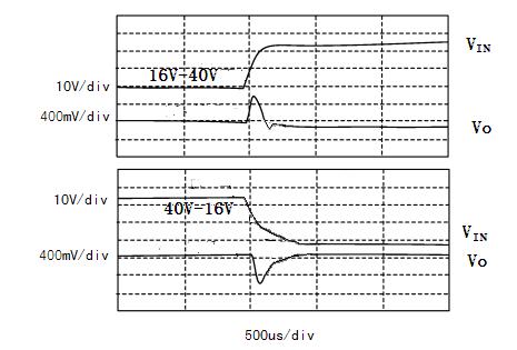
| 22 | Step Line Response Transient(mV pK) | VIN:16V→40V, | -600 | 600 | -600 | 600 | -600 | 600 | ||||
| VIN:40V→16V,Io=Full load | ||||||||||||
| 23 | Step Line Response Recovery(μs) | VIN:16V→40V | ― | 500 | ― | 500 | ― | 500 | ||||
| VIN:40V→16V | ||||||||||||
| Io=Full load | ||||||||||||
| 24 | Start-up Overshoot(mV pK) | VIN:0→28V, | ― | 15 | ― | 50 | ― | 50 | ||||
| Io=Full load | ||||||||||||
| 25 | Start-up Delay (ms) | VIN:0→28V, | ― | 20 | ― | 20 | ― | 20 | ||||
| Io=Full load | ||||||||||||
|
No. |
Parameter |
Conditions |
HSTR28S5 HSTR28S5F |
HSTR28S12 HSTR28S12F |
HSTR28S15 HSTR28S15F |
||||
|
Min |
Max |
Min |
Max |
Min |
Max |
||||
|
1 |
Input Voltage/V |
Low、High、Ambient Temperature |
15 |
50 |
15 |
50 |
15 |
50 |
|
|
2 |
Output Voltage/V |
Io=Full Load |
Ambient |
4.95 |
5.05 |
11.88 |
12.12 |
14.85 |
15.15 |
|
Low/high |
4.88 |
5.12 |
11.70 |
12.30 |
14.62 |
15.38 |
|||
|
3 |
Output current/A |
VIN=15V~50V |
― |
6 |
― |
3.33 |
― |
2.67 |
|
|
4 |
Output Power/W |
|
0 |
30 |
0 |
40 |
0 |
40 |
|
|
5 |
Output Ripple Voltage/mV |
BW=6MHz,Io=Full load |
― |
50 |
― |
50 |
― |
50 |
|
|
6 |
Line Regulation/mV |
VIN=15V~50V,Io=Full |
― |
20 |
― |
20 |
― |
20 |
|
|
7 |
Lode Regulation/mV |
Io=No load to load |
― |
50 |
― |
50 |
― |
50 |
|
|
8 |
Input current/mA |
Inhibit |
― |
6 |
― |
6 |
― |
6 |
|
|
Io=no load |
― |
60 |
― |
60 |
― |
60 |
|||
|
9 |
Input Ripple current/mA |
BW=20MHz,Io=Full load |
― |
50 |
― |
50 |
― |
50 |
|
|
10 |
Efficiency/% |
Io=Full load |
72 |
― |
76 |
― |
77 |
― |
|
|
11 |
Isolation/MΩ |
Input to output or any pin to case(except pin 7、8) at 500V,TA=25℃ |
100 |
― |
100 |
― |
100 |
― |
|
|
12 |
Inhibit Function |
|
0 |
0.7 |
0 |
0.7 |
0 |
0.7 |
|
|
13 |
Inhibit open-circuit Voltage/V |
Io=Full Load |
10 |
14 |
10 |
14 |
10 |
14 |
|
|
14 |
Under-voltage open voltage/V |
Io=Full Load |
12 |
14.8 |
12 |
14.8 |
12 |
14.8 |
|
|
15 |
Under-voltage cut-off voltage/V |
Io=Full Load |
11 |
14.5 |
11 |
14.5 |
11 |
14.5 |
|
|
16 |
Short Circuit Protection |
|
Reduced flow pattern |
Reduced flow pattern |
Reduced flow pattern |
||||
|
17 |
/μF |
TA=25℃ |
― |
1000 |
― |
500 |
― |
500 |
|
|
18 |
Step Load Response Transient(mV pK) |
50%load→full load →50%load |
400 |
550 |
400 |
550 |
400 |
550 |
|
|
19 |
ExternalSynchro frequency range/kHz |
Tc=25℃,full load,TTL electrical level(VIH≥4.5V,VIL≤0.8V),Duty Ratio 40%~60% |
400 |
550 |
400 |
550 |
400 |
500 |
|
|
20 |
Step Load Response Recovery(μs) |
50%load→full load →50%load |
-500 |
500 |
-700 |
700 |
-700 |
700 |
|
|
21 |
Step Line Response Transient(mV pK) |
VIN:16V→40V, VIN:40V→16V,Io=Full load |
― |
500 |
― |
500 |
― |
500 |
|
|
22 |
Step Line Response Recovery(μs) |
VIN:16V→40V VIN:40V→16V Io=Full load |
-600 |
600 |
-900 |
900 |
-900 |
900 |
|
|
23 |
Start-up Overshoot (mV pK) |
VIN:0→28V, Io=Full load |
― |
500 |
― |
500 |
― |
500 |
|
|
24 |
Start-up Delay (ms) |
VIN:0→28V, Io=Full load |
― |
50 |
― |
50 |
― |
50 |
|
|
25 |
Step Load Response Transient(mV pK) |
50%load→full load →50%load |
― |
20 |
― |
20 |
― |
20 |
|


|
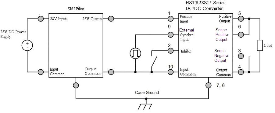
Pin |
Symbol |
Designation |
|
1 |
VI |
Positive Input |
|
2 |
INH |
Inhibit |
|
3 |
Sense- |
SensitiveNegative Output |
|
4 |
GNDO |
OutputGround |
|
5 |
VO |
Positive Output |
|
6 |
Sense+ |
Sensitive Positive Output |
|
7 |
GNDC |
Case Ground |
|
8 |
GNDC |
Case Ground |
|
9 |
SYN |
External Synchro Input |
|
10 |
GNDI |
InputGround |


 |
 |
|
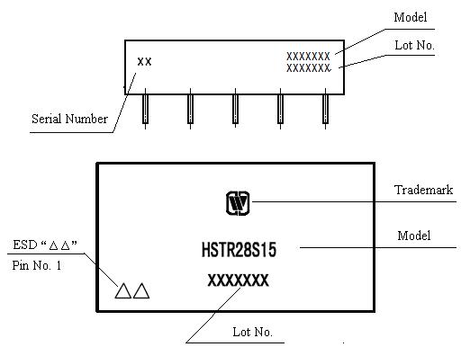
Fig. 11 Bottom View |
Fig. 11 Bottom View |
 |
 |
|
Fig. 13 Bottom View |
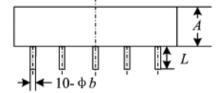
Fig. 14 Side View |
|
Symbol |
Unit/mm |
||
|
Min |
Typical |
Max |
|
|
A |
― |
― |
10.66 |
|
Φb |
0.87 |
1.00 |
1.13 |
|
D |
― |
― |
54.40 |
|
e |
― |
10.16 |
― |
|
e1 |
― |
20.32 |
― |
|
E |
― |
― |
29.0 |
|
L |
5.40 |
― |
― |
|
ΦP |
3.80 |
4.10 |
4.40 |
|
X |
― |
― |
74.00 |
|
X1 |
64.27 |
64.77 |
65.27 |
|
Case Model |
Header |
Header Plating |
Cover |
Cover Plating |
Pin |
Pin Plating |
Seal |
Notes |
|
UPP5429-10j (without flange) |
Cold Rolled Steel(10#) |
Ni |
Kovar (4J42) |
Ni |
Cu –core Compound |
Ni/Au |
Parallel seam |
Ni Plating is for case ground pin |
|
UPP5429-10n (with flange) |
Cold Rolled Steel(10#) |
Ni |
Kovar (4J42) |
Ni |
Cu Compound |
Ni/Au |
Parallel seam |
Ni Plating is for case ground pin |


Subscribe to our weekly newsletter and receive exclusive offers on products you love!
 X
X


 Gold Supplier