HPWM3 Isolated Square Wave Amplifiers

Sales HPWM3 Isolated Square Wave Amplifiers

HPWM3 Isolated Square Wave Amplifier is composed by two completely independent of the pulse amplifier power amplifiers. This PWM Amplifier series of products are made of thick film hybrid integrated process, metal sealed package. Product design and manufacturing meet the requirements of MIL-STD and detailed specifications, the quality level is H-class.
  • Max.Input Vol : 28V
  • Max Current : 10A
  • Function : BRUSHED DC MOTOR CONTROLLER

Product Detail  

1 Features

Input voltage:±20V±0.2V

Continuous output current 5A
Signal supply:±15V±0.15V
Input DC level:-10V~+10V
Include two separate power amplifier circuits
Unique ternary output characteristics
With current negative feedback, the output has constant current source characteristics

2. Applications of HPWM3 Isolated Square Wave Amplifier

DC motor drive control
Drive the reactive load

3. Description of HPWM3 Isolated Square Wave Amplifiers

HPWM3 Isolated Square Wave Amplifier is composed by two completely independent of the pulse amplifier power amplifiers. According to the size of the input control voltage change, the single-way amplifier will output three consecutive amplitudes of the square wave to the motor load, and the circuit has a current negative feedback characteristic, can reduce the motor load loss and improve the anti-jamming capability.
This series of products are made of thick film hybrid integrated process, metal sealed package. Product design and manufacturing meet the requirements of MIL-STD and detailed specifications, the quality level is H-class.

4. Technical Specifications of HPWM3 Isolated Square Wave Amplifier

Form 1: Rated conditions and Operating conditions

Absolute maximum rating

Recommended operating conditions

Positive +Vcc:+16.5V

Negative -Vcc:-16.5V

Positive +Vs:25V

Negative -Vs:-25V

Input voltage Vin:±12V

Storage temperature Tstg:-55℃~125℃

Lead welding temperature(10s)Th:300℃

Junction Temperature Tj:150℃

Positive +Vcc:15V±0.15V

Negative -Vcc:-15V±0.15V

Positive +Vs:20V±0.2V

Negative -Vs:-20V±0.2V

Input voltage Vin:±(0V~10V)

Operating Temperature(Case)Tc:-55℃~125℃


Form 2 Electrical characteristics

Load

Character

+Vcc=15V±0.15V

-Vcc=-15V±0.15V

+Vs=20V±0.2V

-Vs=-20V±0.2V

-55℃≤Tc≤125℃
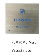
HPWM3

Unit

Min

Max

1

Continuous output current

Full load,VI=1.5

1

-

A

Outputvoltage

Full load

VI=-10V

19

21

V

VI=+10V

-19

-21

Output frequency

-

11

13

kHZ

Linearity

-

95


Symmetry

-

95


2

Continuous output current

Full load,VI=1.5

1

-

A

Outputvoltage

VI=-10V

19

21

V

VI=+10V

-19

-21

Output frequency


11

13

KHZ

Linearity


95


Symmetry


95


5. Lead function descriptions of HPWM3 Isolated Square Wave Amplifier

Lead function descriptions
Fig 2 upward view

Form 3 Pin Designation

No

symbol

Designation

No

symbol

Designation

1

F1

1st output square wave

9

GNDS

Signal ground

2

VI1

1stinput

10

NC

NC

3

FF1

1st negative feedback

11

OUT2

2nd output

4

-Vcc

Power supply -15V

12

GNDP

Power ground

5

+Vcc

Power supply+15V

13

-Vs

Power supply-20V

6

F2

2nd output square wave

14

NC

NC

7

VI2

2ndinput

15

OUT1

1st output

8

FF2

2nd negative feedback

16

+Vs

Power supply+20V


6.Circuit principle frame diagram of HPWM3 Isolated Square Wave Amplifier

The ternary pulse-width power amplifier includes a signal processing circuit, a half-bridge drive circuit and a power amplifier.
Circuit principle frame diagram
Fig 3  signal processing circuit
A triangle wave signal is generated by input control signal and square wave generator circuit , the effect of triangle wave signal and fixed level can generate width modulated square wave signal. Drive circuit can make isolation and distribution for the front width modulated square wave signal, then drive the power tubes, to make power amplifier and drive load for DC motor.

7. Typical Connection Diagram of HPWM3 Isolated Square Wave Amplifier

HPWM3 Isolated Square Wave Amplifier is composed by two completely independent of the pulse amplifier power amplifiers.

Typical Connection Diagram

7.1 Ternary output
The difference between Ternary PWMA and the general PWMA is that the amplifier output of the three states, namely, ternary characteristics, as shown below . Figure 4 shows the input control voltage is 0, the output is positive and negative symmetrical narrow pulse, the average DC is 0, and two output signals are reverse ; When the input voltage reaches half of the input voltage, the negative pulse disappears and becomes a positive unipolar type wide square wave, and the negative pulse duty is reduced. When the input voltage reaches -0.1V, As shown in Figure 5; Input control voltage is increased in positive direction, the output negative pulse duty cycle increases, positive pulse duty cycle decreases, when the input voltage reaches +0.1V or so, the positive pulse disappears and becomes negative type wide square wave, as shown in Figure 6.

The amplifier output two waveforms when the input control voltage is 0

Fig 4 The amplifier output two waveforms when the input control voltage is 0.

The amplifier output two waveforms a point waveforms when input control voltage is negative.(V<-0.1V)
Fig 5 The amplifier output two waveforms a point waveforms when input control voltage is negative.(V<-0.1V)

The amplifier output two waveforms a point waveforms when input control voltage is positive.(V>0.1V)
Fig 6 The amplifier output two waveforms a point waveforms when input control voltage is positive.(V>0.1V)

7.2 Power supply bypass
Power supply should have sufficient bypass capacitors to ensure proper operation, otherwise it may be unstable and reduce efficiency, and the output may be oscillated. ±20V power supply should connect an at least 1uF ceramic capacitor paralleled with a low value ESR capacitor, the capacitance should be at least 10uF/A ; for ±15V power supply also requires a 0.1uF~0.47uF ceramic capacitor paralleled with a low ESR value of 6.8uF~10uF  bypass capacitor, All bypass capacitors should be connected as close as possible to the corresponding power supply root.

7.3 Output constant current characteristics:
Figure 7 circuit, assuming that the input DC control voltage signal is Vi, the output DC current is Io, then the circuit gain A=Io/Vi, because it is a series of negative feedback, F1 is the symmetrical positive and negative square wave when average DC voltage is 0, then Vi/R1≈Uf/R3≈Rf/R3, launched Io/Vi=R3/R1Rf, the circuit gain A=Io/Vi=R3/R1Rf, the formula shows that the circuit gain is basically independent of the carrier gain Aod and the load DC motor R1 and other parameters, that is, when the input DC level is stable and the DC motor changes, the output square wave duty cycle will change, thus ensuring the output DC Io which improves the ability to adapt to the motor load, so that the output has a constant current source characteristics.

Current series negative feedback circuit
Fig 7 Current series negative feedback circuit

8. Package Specifications of HPWM3 Isolated Square Wave Amplifier

Package Specifications
Application notes please refer to the appendix, must read it carefully.
Leave A Message
If you are interested in our products and want to know more details,please leave a message here,we will reply you as soon as we can.
X

Home

Supplier

Leave a message

Leave a message

If you are interested in our products and want to know more details,please leave a message here,we will reply you as soon as we can.