MPWM100-10 Large power PWMA

Sales MPWM100-10 Large power PWMA

  • Max.Input Vol : 100V
  • Function : BRUSHED DC MOTOR CONTROLLER
  • Max Current : 10A

Product Detail  

1. Features

Customer Design

Wide input voltage:16V~100V
±10V Analog DC signal input
Max continuous input current 50A
The product includes a current limiting circuit
Work in the rated power without the need for external radiator

2. Applications of MPWM100-10 Large power PWMA

DC motor drive control
Drive the reactive load

3. Descriptions of MPWM100-10 Large power PWMA

MPWM100-10 is a switching mode PWMA,It can provide 1KW maximum load power for the load; the product needs two power supplies, +15V for the small signal control circuit power supply; 16V-100V motor power supply for the internal H bridge; input circuit control signal for the bipolar analog DC input(±10V) flat signal;Ouput pulse square wave signal frequency 0.9~2KHz.  When the output current is greater than 50A, the circuit will close the four power driving tubes of the H bridge circuit to make the product into the protection state. The circuit can back to work normally again until restart.
MPWM100-10 PWMA using excellent structural design to ensure the rated power conditions within the product dissipation power can be better passed to the shell without the need for external cooling device, easy to use and easy to install. The coonection of the product and system only needs to be done through the connection socket, without any external components.

4. Technical Specifications of MPWM100-10 Large power PWMA

Form 1 Electrical characteristics

Absolute Maximum Ratings

Recommended working conditions

Supply voltage +Vs:100V

Supply voltage +Vcc:16V

Internal power loss:380W(Total power consumption of two tubes)

Storage temperature:-55℃~+105℃

Operating temperature(Tc):-40℃~+85℃

Input voltage +PWM:±10V

Supply voltage +Vs:16V~100V

Supply voltage +Vcc:15V

Input voltage +PWM:±2V
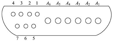
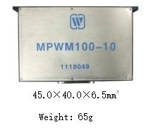


5. Lead function description of MPWM100-10 Large power PWMA


Fig 2 Bottom view

Form 3 Lead description

No.

Symbol

Function

No.

Symbol

Function

1

1

Control signal ground

8

A1

+100V

2

2

+15V

9

A2

PowerGround

3

3

NC

10

A3

Output 1

4

4

Control signal

11

A4

Output 2

5

5

+15V ground

12

A5

Current protect Shutdown

6

6

Functiondirection signal terminal A

13

A6

NC

7

7

Functiondirection signal terminal B


6. Circuit block diagram of MPWM100-10 Large power PWMA

Circuit block diagram
Fig 3  Circuit block diagram

7. Typical Connection Diagram of MPWM100-10 Large power PWMA


Typical Connection Diagram
Application notes please refer to the appendix, must read it carefully.
Leave A Message
If you are interested in our products and want to know more details,please leave a message here,we will reply you as soon as we can.
X

Home

Supplier

Leave a message

Leave a message

If you are interested in our products and want to know more details,please leave a message here,we will reply you as soon as we can.