HPA1000 Isolated Pulse Width Modulation Amplifiers

Sales HPA1000 Isolated Pulse Width Modulation Amplifiers

  • Max.Input Vol : 100V
  • Function : BRUSHED DC MOTOR CONTROLLER
  • Max Current : 10A

Product Detail  

1. Features

Customized design

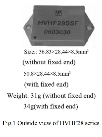
Wide range supply voltage VS:16V~100V
TTL Wide square wave signal input
Continuous output current:30A


2. Scope of application of HPA1000 Isolated Pulse Width Modulation Amplifier

DC motor drive control
Drive the reactive load

3. Descriptions of HPA1000 Isolated Pulse Width Modulation Amplifier

HPA1000 isolated pulse width modulation amplifier is made of thick film hybrid integrated process with metal sealed shell package. Its input signal is TTL wide square wave ,motor power supply voltage can reach up to 100V and output peak current can reach 40A; Product’s design and manufacturing meet the MIL-STD and detailed specifications of the product requirements, the quality level is H-class.

4. Technical Specifications of HPA1000 Isolated Pulse Width Modulation Amplifier

Form 2 electrical characteristics

No

Character

Conditions

VCC=5V±0.25V

VS=28V±1V

-55℃≤Tc≤125℃

RL=10Ω±2Ω

HPA1000

Sym

Group

Min

Max

1

Static operating current/ICC

VCC=15V±0.5V,VI=5V±0.5V

22.5KHZ square wave, Duty cycle 50%±10%

1/2/3

-

70

mA

2

Switching frequency /fo

Io=5A±0.5A

4/5/6

-

22.5

KHZ

3

Output square wave voltage amplitude /VOA

Io=5A±0.5A

1

23

32

V

4

Continuous output current /IO

VS=100V±10V

1

9.8

10.2

A

5

Max input signal frequency /fimax

IO=5A±0.5A

4/5/6

22

23

KHZ

6

The duty cycle /q

IO=5A±0.5A

4/5/6

5

95

%

7

Efficiency

VS=50V~55V,RL=5Ω±0.5Ω

1

95

-

%


5. Lead function descriptions of HPA1000 Isolated Pulse Width Modulation Amplifier

Lead function descriptions
Fig 2 upward view

Form 3 Pin Designation

No

symbol

Designation

No

symbol

Designation

1

NC

NC

7

GNDVS

VS Negative

2

+VCC

VCC Positive

8

OUTB

Output B

3

VI

Signal input

9

+VS

VS Positive

4

NC

NC

10

NC

NC

5

GND

iutput Ground

11

OUTA

Output A

6

NC

NC

12

GNDVS

Output ground


6. Circuit principle frame diagram of HPA1000 Isolated Pulse Width Modulation Amplifier

Circuit principle frame diagram
Fig 3  Circuit principle frame diagram

7. Typical Connection Diagram of HPA1000 Isolated Pulse Width Modulation Amplifier

Typical Connection Diagram
Fig 4  HPA1000 Typical connection Diagram
Notes:Power supply VS should have sufficient bypass capacitors to ensure proper operation, otherwise it may be unstable and reduce efficiency, and the output may be oscillated. Vs power supply should connect with a 1uF at least ceramic capacitor paralleled with a low ESR value bypass capacitor. The capacitance should be at least 10uF/A. for VCC also requires a 0.1uF~0.47uF ceramic capacitor and a low ESR value of 6.8uF~10uF parallel bypass capacitor, All bypass capacitors should be connected as close as possible to the corresponding power supply root.

8. Package Specifications of HPA1000 Isolated Pulse Width Modulation Amplifier

Circuit package outlines is shown in Fig 5 .
Package Specifications
Fig 5 upward view
Notes:Dimensional tolerances not shown in the Fig:±0.5mm  Unit:mm
Application notes please refer to the appendix, must read it carefully
Leave A Message
If you are interested in our products and want to know more details,please leave a message here,we will reply you as soon as we can.
X

Home

Supplier

Leave a message

Leave a message

If you are interested in our products and want to know more details,please leave a message here,we will reply you as soon as we can.