Resolver to Digital Converters (HSDC/HRDC27 Series)

Sales Resolver to Digital Converters (HSDC/HRDC27 Series)

Resolver to Digital Converters (HSDC/HRDC27 Series) is the digital to synchro converters or resolver to digital converters for continuous tracking of type II servo loop, it parallelly latches and outputs 12-bit or 14-bit natural binary coded data with 32-line dual-in-line metal package, features the advantages of small volume, light weight and high reliability etc., it is widely applied in such automatic control system as Radar system, navigation system, etc.

The operating power adopts ±15V and + 5V DC power. There are two types of output signal: three-line synchro and reference signal (SDC converter) or four-line resolver and reference signal (RDC converter); the output adopts parallel digital codes of binary system.

  • Accuracy : ±8.5 arc min (12bits) ,±5.3 arc min (14bits)
  • Power supply voltage : +5V,±15V
  • Resolution : 12 or 14 bits

Product Detail  

1.Features (see Fig. 1 for outside view, and Table 1 for models) of Synchro/Resolver-Digital Converter (HSDC/HRDC27 Series)

Resolution: 12 bits, 14 bits
High tracking speed
Hybrid integration, metal case
Three-state latch output
With velocity signal Vel output
Indefinite compatibility with AD1740 series

2.Scope of application of Synchro to Digital Converters or Resolver to Digital Converters (HSDC/HRDC27 Series)

Servo system; antenna system; angle measurement; simulation technology; cannon control; control of industrial machine tools

3.Description of Synchro to Digital Converters or Resolver to Digital Converters (HSDC/HRDC27 Series)

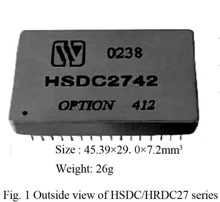
HSDC/HRDC27 series is the digital to synchro converters or resolver to digital converters for continuous tracking of type II servo loop, it parallelly latches and outputs 12-bit or 14-bit natural binary coded data with 32-line dual-in-line metal package, features the advantages of small volume, light weight and high reliability etc., it is widely applied in such automatic control system as Radar system, navigation system, etc.
The operating power adopts ±15V and + 5V DC power. There are two types of output signal: three-line synchro and reference signal (SDC converter) or four-line resolver and reference signal (RDC converter); the output adopts parallel digital codes of binary system.


Table 2  Rated conditions and recommended operating conditions

Absolute max. rated value

Supply voltage Vs: ± 17.5V

Logical voltage VL: +5.5V

Storage temperature range: -55℃~+125℃

Recommended operating conditions

Supply voltage Vs: ± 5V

Logical voltage VL: 5V

Effective value of reference voltage VRef: ±10% of nominal value

Validity of signal voltage V1*: ±5% of nominal value

Reference frequency f*: 50Hz~2.6kHz

Operating temperature range TA: -40~+85℃,-55~+105℃

Note: * indicates it can be customized as per user’s requirement.


This series is a digital converter of modular structure for synchro resolver with built-in solid-state SCOTT isolation converter, designed according to the principle of Model II servo, and can realize continuous tracking and conversion.
Differential isolation input and data output is three-state latch mode, suitable for analog signal/digital signal conversion of three-wire type synchro and four-wire resolver. With fast conversion speed and stable and reliable performance, this device can be widely applied in angle measurement and automatic control system.
This product is made by the thick-film hybrid integration process and is 32-wire DIP totally sealed metal package. Both the design and manufacture of the product satisfy the requirements of GJB2438A-2002 “General specification for packages of hybrid integrated circuits” and specific specification of the product.

4.Electrical performance (Table 2, Table 3) of Synchro to Digital Converters or Resolver to Digital Converters (HSDC/HRDC27 Series)


Note:
  • For converters with frequency of 50kHz, 2kHz and others, the dynamic parameters are different, and they can be provided as per customers' requirements;
  • Customization is available.

5.Operating principle of Synchro to Digital Converters or Resolver to Digital Converters (HSDC/HRDC27 Series)

The synchro input signal (or input signal of resolver) is converted into the orthogonal signal through internal differential isolation:

Where, θ is analog input angle

The digital angle φ of internal reversible counter of these two signals are multiplied in the multiplier of Sine and Cosine functions and are error treated:

The signals are sent to voltage controlled oscillator after amplification, phase discrimination and integration filtration, if θ-φ≠0, the voltage controlled oscillator will output pulse to change the data in the reversible counter, till θ-φ becomes zero within the accuracy of the converter, during this process, the conversion tracks the change of input angle θ all the time.
Synchro/Resolver-Digital Converter (HSDC/HRDC27 Series)-3
Methods of data transfer and time sequence

There are two methods for reading out the valid data of converter:

(1) Inhibit method (synchronous reading):

A: the converter is connected to 16-bit bus. Byse 1 is connected to logic “1”.
Inhibit is set to logic “0” from logic “1” (data locking), wait for 1μs; set Enable to logic “0”, the latch data inside the converter is allowed to be output; read 12-bit or 14-bit data; set Inhibit to logic “1” so as to get ready for reading next valid data (see the time sequence diagram of 16-bit transfer).

B: the converter is connected to 8-bit bus, D1~D8 bit are connected to data bus, and the rest are empty.
Inhibit is set to logic “0” from logic “1” (data locking), wait for 1μs; set Enable to logic “0”, the latch data inside the converter is allowed to be output; if Byse1 is set to logic “1”, the converter directly reads the higher 8-bit data, if Byse1 is set to logic “0”, the converter reads the rest bits, automatically adds zero for incomplete bits; set Inhibit data locking control (Inhibit signal) to logic “1” in order to get ready for reading next valid data (see Fig. 3 and Fig. 4 for 8-bit transfer time sequence)

Synchro/Resolver-Digital Converter (HSDC/HRDC27 Series)-9
(2) Busy method (asynchronous reading):
In asynchronous reading mode, Inhibit data locking control (Inhibit signal) is set to logic “1” or empty, whether the internal loop is always in the stable state or whether the output data is valid shall be determined through the state of busy signal Busy. When Busy signal is at high level, it indicates the data is being converted, and the data at this time is unstable and invalid; when Busy signal is at low level, it indicates the data conversion has been completed, and the data at this time is stable and valid. Once high level occurs in Busy during reading, the reading of this time is invalid. In asynchronous reading mode, Busy output is pulse train of TTL level, the width between is related to rotational speed. Likewise, there are also 8-bit and 16-bit two use methods of bus, at the time of valid data output, data reading is also controlled by Enable , refer to time sequence diagram of data transfer (Fig.5 and Fig.6)
Synchro/Resolver-Digital Converter (HSDC/HRDC27 Series)-12
Notes:
  • For 12-bit converter, pin 13 and 14 are left unconnected.
  • For SDC converter, pin 17 is left unconnected.
  • Power supply: ±15V, +5V, GND, the power shall not be connected reversely, otherwise, components will be damaged.
  • Binary digital output: 12 bits and 14 bits, respectively.
  • RHi, RLo: excitation signal input.
  • S1, S2, S3 and S4: signal input of synchro or resolver.(S4 not used for the synchro)
  • Busy: busy signal
This signal indicates whether the binary number output from the converter is valid or not. When Busy is at high level, it indicates the converter is carrying out data conversion, the data output at this time is invalid; when Busy is at low level, the data in the converter is stable and the data output at this time is valid.
  • Enable Data gating
This pin is the input pin of control logic, its function is to output data to the converter to realize three-state control. Low level is valid, the output data of converter occupies the data bus. When it is at high level, the data output pin of converter is in three states, the device does not occupy the bus.
  • Inhibit data locking control (Inhibit signal)
This pin is the input pin of control logic, its function is to output data externally to the converter to realize optional latching or bypass control.
At high level, the output data of the converter directly outputs without latching; at low level, the output data of the converter is latched, the data is not updated, but the internal loop is not interrupted, and tracking is working all the time. Inhibit data locking control (Inhibit signal) has connected high resistance (whether the device adopts data bus to output the data depends on the state of ).
Enable
  • Byse1: bit selection terminal
This is a control terminal specially designed for connecting the converter with 8-bit data or 16-bit data bus. When the converter is connected with 16-bit data bus, Byse1 is pulled up internally, the converter can directly output 12-bit or 14-bit data; when the converter is connected with 8-bit data bus, Byse1 is at a high level, the converter outputs data of higher 8 bits (D1~D8), when Byse1 is at low level, the converter outputs data of the rest bits (copying the data of the rest bits to bit D1~D8), and automatically fills zero for the data of short bits. It shall be noted that it is only needed to connect D1~D8 when the converter is connected with 8-bit data bus, other data pins are left unconnected.


8.Table of weight values of Synchro to Digital Converters or Resolver to Digital Converters (HSDC/HRDC27 Series)

Synchro/Resolver-Digital Converter (HSDC/HRDC27 Series)-19

9.Connection diagram for typical application (Fig. 9) of Synchro to Digital Converters or Resolver to Digital Converters (HSDC/HRDC27 Series)

Besides being directly used in precise measurement of rotational angle of the synchro or resolver, the shaft angle converter can also constitute two-speed measurement system or other digital measurement control system of higher precision. Fig.9 is an example of two-speed system composed of the converter. The two-speed system established on the principle of combination of coarse and precise measurement has a higher conversion precision, Fig.9 shows the two-speed conversion system composed of two synchros (or resolvers) coupled through the gearbox, two SDC converters and a two-speed processor HTSL19, its output reaches 19 bits. Synchro/Resolver-Digital Converter (HSDC/HRDC27 Series)-20

10.Package specifications (unit: mm) (Fig.10) of Synchro to Digital Converters or Resolver to Digital Converters (HSDC/HRDC27 Series)

Bottom view Front view
Synchro/Resolver-Digital Converter (HSDC/HRDC27 Series)-21
Fig.10 Outside view of package
Table 5  Case materials
Case model Header Header plating Cover Covering plating Pin material Pin plating Sealing style Notes
UP4529-32a Kovar (4J29) Au Iron/ nickel alloy (4J42) Au Kovar (4J29) Au Matched seal Plating of pin 23 is Au

11.Part numbering key (Fig. 11) of Synchro to Digital Converters or Resolver to Digital Converters (HSDC/HRDC27 Series)


Synchro/Resolver-Digital Converter (HSDC/HRDC27 Series)-22
Application notes:
  • Supply the power correctly, upon power-on, be sure to correctly connect the positive and negative pole of the power supply for fear of burning.
  • Connection of the converter
±15V, +5V and GND shall be connected to corresponding pins on the converter, notice that the polarities of the power supply must be correct, otherwise, components may be damaged. It is recommended to connect 0.1μF and 6.8μF bypass capacitance in parallel between each power supply terminal and ground. Signal and excitation source are allowed to be connected to S1, S2, S3 and S4 and RHi and RLo within an error of 5%. It is only needed to connect D1~D8 when the converter is connected with 8-bit data bus, other data pins are left unconnected.
When the converter is connected to 16-bit data bus, D1~D14 or (D1~D12) shall all be connected.
The signal input shall match the phase of the excitation so that they can be correctly connected with the converter, their phases are as follows:

For the synchro:
Synchro/Resolver-Digital Converter (HSDC/HRDC27 Series)-23
For the resolver:
Synchro/Resolver-Digital Converter (HSDC/HRDC27 Series)-24
  • Upon assembly, the bottom of the product shall fit to the circuit board closely so as to avoid damage of pins, and shockproof provision shall be added, if necessary.
  • When the user places an order for the product, detailed electric performance indexes shall refer to the relevant enterprise standard.
Leave A Message
If you are interested in our products and want to know more details,please leave a message here,we will reply you as soon as we can.
X

Home

Supplier

Leave a message

Leave a message

If you are interested in our products and want to know more details,please leave a message here,we will reply you as soon as we can.