1.General requirements
(1).Before the cable is laid, it should be checked whether the cable is intact and whether the insulation resistance meets the standard requirements;
(2).When the cable is laid, the spacing between the fixing points can be fixed at the value recommended in the following table, except for the bracket laying fixed at the bracket. In the open application part, if the same direction of the cable large, medium and small specifications have, from the neat, beautiful consideration, can be fixed according to the minimum specification cable standard requirements, can also be fixed in the file distance. When the cable is laid inclined and the cable is 30° and below in the vertical direction, it is fixed according to the vertical spacing; When greater than 30°, fix it horizontally;
|
Cable diameter |
D<9 |
9《D<15 |
D》15 |
|
|
The maximun distance between fixed points |
level |
600 |
900 |
1500 |
|
Vertical |
800 |
1200 |
2000 |
|
(3).When the cable is laid, at the corner, on both sides of the intermediate connector, the conditional fixation should be fixed;
(4).When calculating the length required to lay a cable, a margin of 1% should be considered;
(5).Appropriate protective measures should be taken for parts of the cable that may suffer mechanical damage during operation;
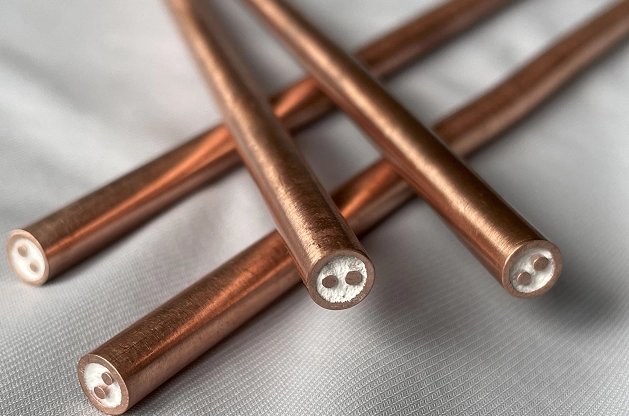
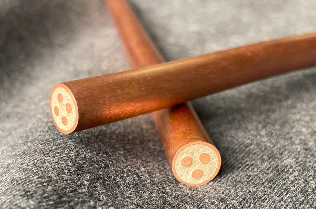
(6).When laying single-core cables, they should be laid root by root, and after each group is aligned and straightened, then the alignment and lashing are made, and the lashing spacing is 1-1.5m.
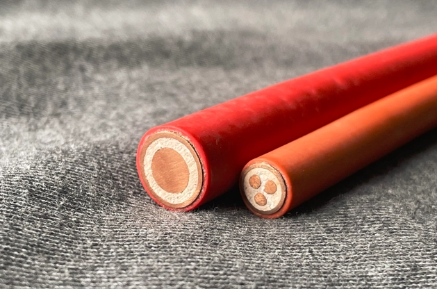
(7).When the cable is laid in an environment with corrosive effect on the copper sheath, or when partially buried or through the pipe, the PVC outer sheath or low-smoke halogen-free outer sheath should be used.
(8).During the wiring process, the cable should be temporarily sealed immediately after it is sawn.
(9).When the entire length of the cable is laid in a straight line or when the electrical appliances used for connection may vibrate, an expansion ring should be set up where it is allowed.
(10).Generally, mineral insulated cables do not need to be threaded through. Also, single core cables are not allowed to be laid with metal tubes alone.
|
Specification of Penetration Tube |
|||
|
Cable specification |
2 |
3 |
4 |
|
1*10 |
Sc25 |
Sc25 |
Sc40 |
|
1*16 |
Sc25 |
Sc25 |
Sc50 |
|
1*25 |
Sc32 |
Sc32 |
Sc50 |
|
1*35 |
Sc32 |
Sc32 |
Sc65 |
|
1*50 |
Sc40 |
Sc40 |
Sc65 |
|
1*70 |
Sc40 |
Sc40 |
Sc80 |
|
1*95 |
Sc50 |
Sc50 |
Sc80 |
|
1*120 |
Sc50 |
Sc50 |
Sc100 |
|
1*150 |
Sc65 |
Sc65 |
Sc100 |
|
Multi-core cable |
|||||
|
Cable specification (light duty) |
Cable specification |
Cable specification (heavy duty) |
Cable specification |
Cable specification (heavy duty) |
Cable specification |
|
2*1.0 |
Sc15 |
2*1.5 |
Sc15 |
4*1.5 |
Sc15 |
|
2*1.5 |
Sc15 |
2*2.5 |
Sc15 |
4*2.5 |
Sc20 Sc15 |
|
2*2.5 |
Sc15 |
2*4 |
Sc20 |
4*4 |
Sc20 |
|
2*4 |
Sc15 |
2*6 |
Sc20 |
4*6 |
Sc20 |
|
3*1.0 |
Sc15 |
2*10 |
Sc20 |
4*10 |
Sc25 Sc20 |
|
3*1.5 |
Sc15 |
2*16 |
Sc25 |
4*16 |
Sc32 Sc25 |
|
3*2.5 |
Sc15 |
2*25 |
Sc32 |
4*25 |
Sc40 |
|
4*1.0 |
Sc15 |
3*1.5 |
Sc15 |
7*1.5 |
Sc20 |
|
4*1.5 |
Sc15 |
3*2.5 |
Sc15 |
7*2.5 |
Sc20 |
|
4*2.5 |
Sc15 |
3*4 |
Sc20 |
10*1.5 |
Sc25 |
|
7*1.0 |
Sc15 |
3*6 |
Sc20 |
10*2.5 |
Sc25 |
|
7*1.5 |
Sc15 |
3*10 |
Sc25 |
12*1.5 |
Sc25 |
|
7*2.5 |
Sc20 |
3*16 |
Sc25 |
12*2.5 |
Sc25 |
|
|
|
3*25 |
Sc32 |
19*1.5 |
Sc32 |
(11).It can be laid in the ground, but it is best not to have a neutral head, if it is unavoidable, the joint needs to be waterproof or set up a cable well.
(12).For large-section single-core cables, eddy current elimination measures should be taken when used in AC power grids. Under the action of alternating current, lateral eddy currents will be formed on the copper sheath, which will cause energy loss. When the line load is particularly large and more than two sets of cables are required, two or more sets of cables can be arranged in the form of Figure 1 a.b, but a distance of twice the outer diameter of the cables should be left between each set, and each set of cables should be The wiring positions should be the same. In addition, when the cables are fed into the distribution box and cabinet, holes should be drilled on the board surface of the cabinet to fix the cable. Similarly, in order to prevent the cable from generating vortices on the iron surface of the box and cabinet, the board surface of the cabinet should be pressed according to the The method shown in Figure 2 is to open the hole, or add a non-magnetic material to the partition to fix the cable. This kind of bracket is generally made of aluminum busbar or copper busbar and punched. When the bracket is made of flat steel or angle steel, it is also The holes should be drilled according to the above method to prevent the generation of eddy currents.

Subscribe to our weekly newsletter and receive exclusive offers on products you love!
 X
X


 Gold Supplier