
> Power Supply: DC12V; DC24V
> Operation Delay Time: 0sec., 2.5sec., 5sec., 9sec.
> Holding forces: 600lbs
> Weight: 3kg
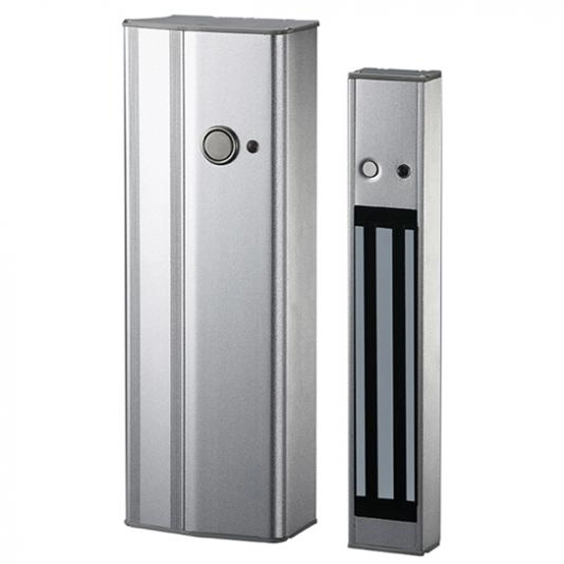
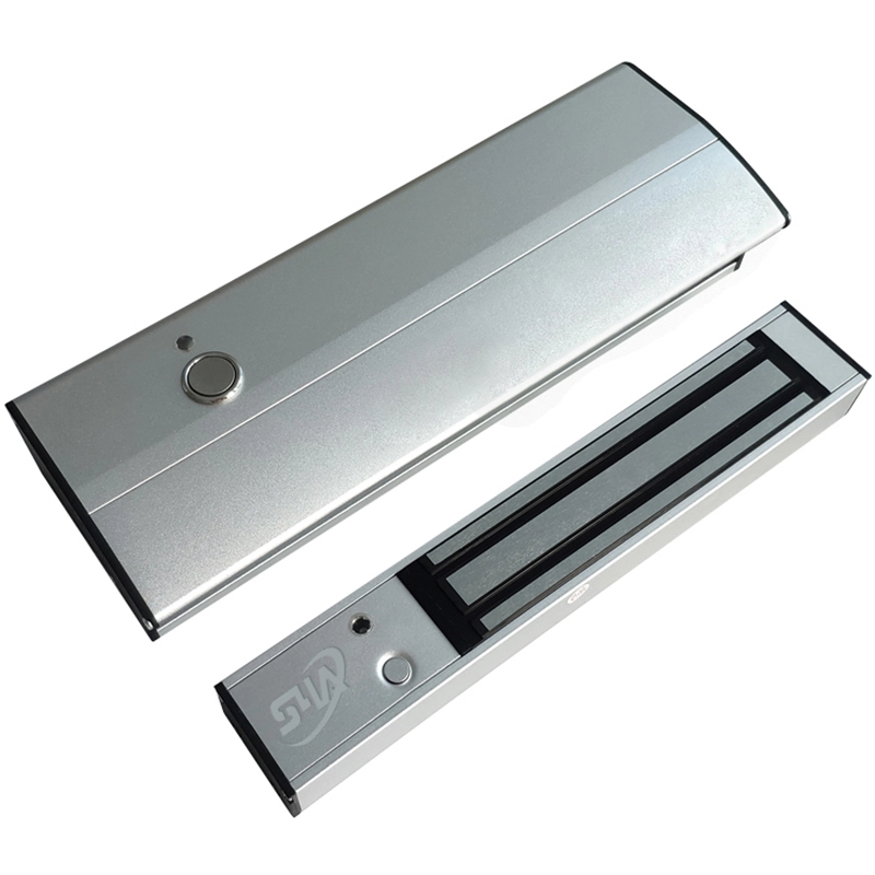
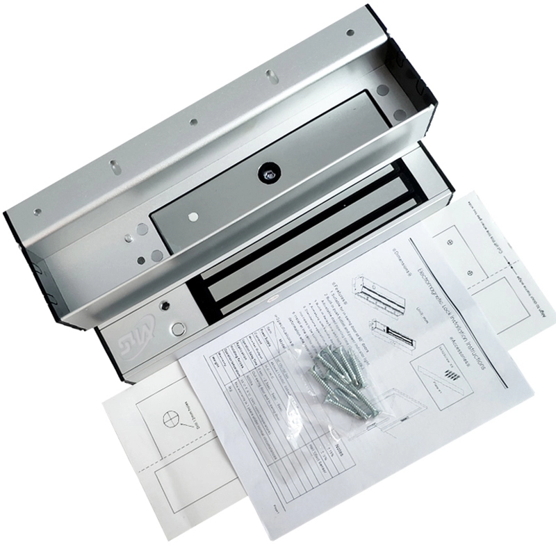
Door Handle Magnetic Lock
Model No.: EL-250
What is Electromagnetic Lock?
Electromagnetic locks consist of an armature and a coil assembly, which become magnetized when an electric current passes through them. This magnetic field secures the door and electronically controls when doors are locked and unlocked.
Electromagnetic locks are fail-safe by design.
Features
1. Suitable for in-swing door or 90 doors
2. Built-in push button and power indicator light.
Adjustable door opening time (0~9 seconds.)
3. Built-in delay time and lock monitor output.
4. Armature with handle design.
5. Standalone operation when power is on and it does not need to be controlled by proximity reader.
6. Install at the center of the door leaf to prevent deformation whenever it is locked or unlocked.
Model | EL-250 | Notes |
Power Supply | DC 12V / DC 24V | ± 15% |
Current | 450mA / 12VDC 235mA / 24VDC | ± 15% |
Monitor Output | N.O / N.C | Hall Effect Sensor |
Operation Delay Time | 0 sec., 2.5sec., 5sec., 9sec. | |
Application | Out-swing door and In-swing door | |
Holding forces | 600lbs | |
Operation temperature | 35℃ ±5℃ (30℃ room temperature) | |
Warranty | The warranty is 1 year under normal circumstances | |
Weight | 3 kg |

Attention
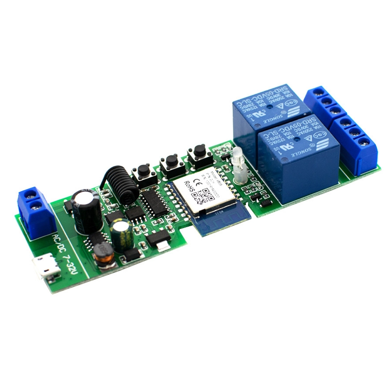
1. Door open buttons have both built-in and external inputs. Please use both V- and P.S. Points for the external door open button. Both built-in and external door open buttons are able to be used at the same time. (Please refer to the diagram above) .
2. Door Lock status (N.O/N.C) as Relay output. Maximum load of 1A@24VAC.
3. The indicator light is green when the door is locked, or else the door did not close tight.
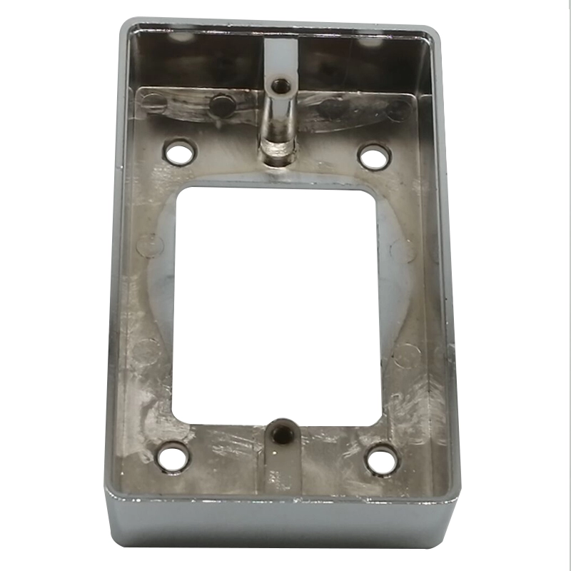
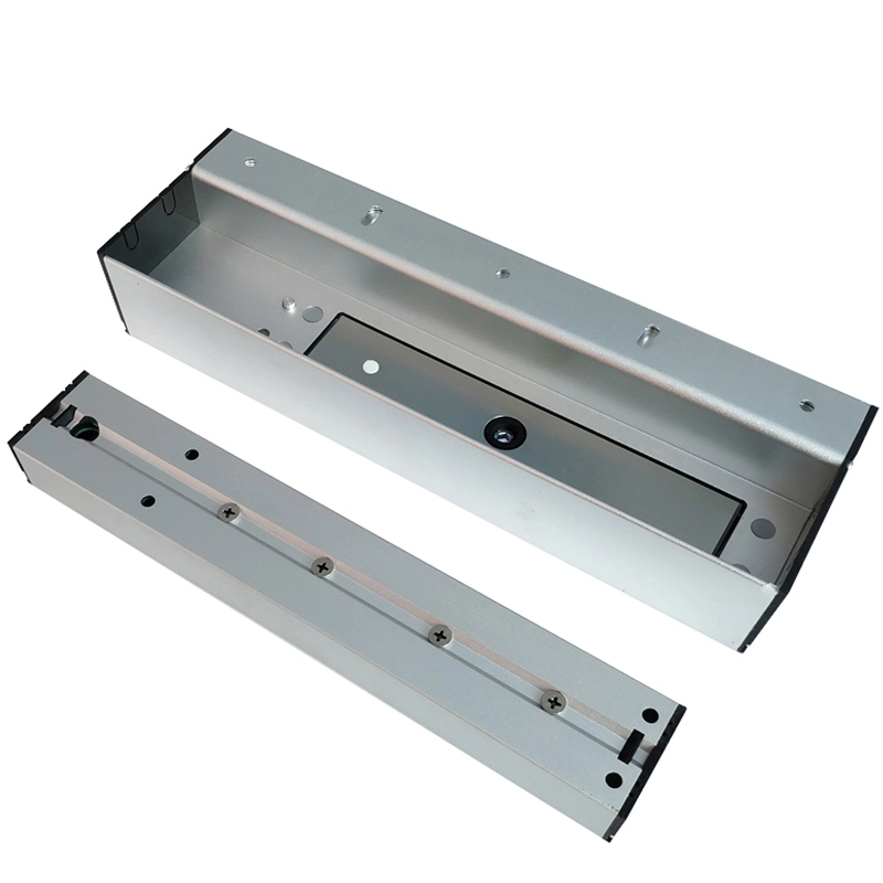
Installation
Step 1:
Please stick the sticker on the desired mounting position (Please refer to Fig.1) and drill holes
according to the sticker's indicated positions. Remove the sticker after drilling a hole for wiring.
Step 2:
Remove both sides of the lock's covers A and pull out the B.(Please refer to Fig.2- Fig.4)
Use screws to screw the body lock tight on the appropriate position. Place all covers back in order.

Step 3:
Remove the upper cover (C) of the handle and then the lower cover(C-1) by removing two screws (A-1 B-1) to pull out the plate(D). (Please refer to Fig5-Fig6)
Step 4:
Use two attached screws to screw the handle onto the appropriate position of the installation holes when D is pulled out. (Please refer to Fig 7) Do not screw tight as to adjust both handle and body lock positions well by closing the door several times to make sure both of them are matched. Screw the remaining three screws when they are matched.

Step 5:
Slide plate(P) when positioning and adjusting screws are tightened. Assemble the handle and its body's back in order.
Installation diagram

Optional plate
AN optional EL-250P plate (thickness of 3.6mm) is available to achieve the optimum height of both the door frame and door leaf when the unit is installed.

Dimensions


Subscribe to our weekly newsletter and receive exclusive offers on products you love!
 X
X


 Gold Supplier